
add a heatsink to the jfets and increase bias far as you can, thus increasing power in class A
Can you recommend a type of heatsink that works well with the JFET form factor?
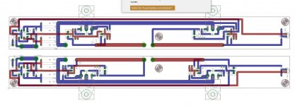
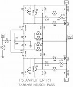
The Layouts based on the F5 R1 Schematics (with P3)
I`ve build an working amp with that Layouts but,
Please befor using it, recheck, Layouts & schematics for yourself.
For tips how i do Toner Transfer with 2 sided PCB PM me.
If you find Errors of have some Kind of improvement,
Reply here.
I`ve build an working amp with that Layouts but,
Please befor using it, recheck, Layouts & schematics for yourself.
For tips how i do Toner Transfer with 2 sided PCB PM me.
If you find Errors of have some Kind of improvement,
Reply here.
Attachments
I made the heatsinks for my JFETs out of a sheet of copper I bought at Home Depot. They sell it in the hardware department. It's soft enough to cut with scissors.
Hi all,
I need some help on my F5 build. It’s not biasing up correctly. I don’t know if this thread is a good place for general support but I’ll post here and see.
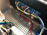
Basically it’s a standard F5 build with DIY audio store parts to the V3 schematic. The voltage rails are good (brought them up slowly on a variac) and went to start creeping the bias up but after several turns of the pots there was no change in current as measured across the source resistors. I was nervous so I have not tried turning them up ALL the way. I disconnected the PS rails and measured resistance across R5 and R6 while adjusting the pots to see if the resistance was changing. On both boards one pot seems to adjust from 0 to 500 ohms (P1 on the left channel and P2 on the right), the other tops out at ~115. I measured every resistor value before installation and I think the solder work looks good. What range should I be seeing on the pots?
I’ve attached the obligatory pictures.
I need some help on my F5 build. It’s not biasing up correctly. I don’t know if this thread is a good place for general support but I’ll post here and see.
Basically it’s a standard F5 build with DIY audio store parts to the V3 schematic. The voltage rails are good (brought them up slowly on a variac) and went to start creeping the bias up but after several turns of the pots there was no change in current as measured across the source resistors. I was nervous so I have not tried turning them up ALL the way. I disconnected the PS rails and measured resistance across R5 and R6 while adjusting the pots to see if the resistance was changing. On both boards one pot seems to adjust from 0 to 500 ohms (P1 on the left channel and P2 on the right), the other tops out at ~115. I measured every resistor value before installation and I think the solder work looks good. What range should I be seeing on the pots?
I’ve attached the obligatory pictures.
Attachments
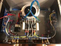
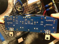
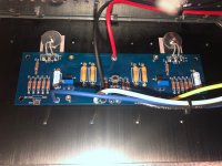
Looks nice! It can be a little hard to measure those resistances in circuit because the active devices. Are the npn and pnp transistors oriented correctly? Cannot see in the picture, but it might be worth double checking.
Did you adjust both pots 1/4 or 1/2 turn each as you bias up? If you did only one at a time, this might be your issue.
Did you adjust both pots 1/4 or 1/2 turn each as you bias up? If you did only one at a time, this might be your issue.
On both boards one pot seems to adjust from 0 to 500 ohms (P1 on the left channel
and P2 on the right), the other tops out at ~115.
Make sure the 5k and 200R pots are in the right places.
Indeed, you need a couple of volts VGS on the MOSFETs before they start conducting. So initially you will measure no current as you start at zero.
If you built it with 32V rails you'll need to recalculate the resistor values in the current limiting circuit. Otherwise the BJTs will be turned fully on and you'll never bias it up. I removed mine.Hi all,
I need some help on my F5 build. It’s not biasing up correctly. I don’t know if this thread is a good place for general support but I’ll post here and see.
Basically it’s a standard F5 build with DIY audio store parts to the V3 schematic. The voltage rails are good (brought them up slowly on a variac) and went to start creeping the bias up but after several turns of the pots there was no change in current as measured across the source resistors. I was nervous so I have not tried turning them up ALL the way. I disconnected the PS rails and measured resistance across R5 and R6 while adjusting the pots to see if the resistance was changing. On both boards one pot seems to adjust from 0 to 500 ohms (P1 on the left channel and P2 on the right), the other tops out at ~115. I measured every resistor value before installation and I think the solder work looks good. What range should I be seeing on the pots?
I’ve attached the obligatory pictures.
Looks nice! It can be a little hard to measure those resistances in circuit because the active devices. Are the npn and pnp transistors oriented correctly? Cannot see in the picture, but it might be worth double checking.
Did you adjust both pots 1/4 or 1/2 turn each as you bias up? If you did only one at a time, this might be your issue.
Thanks. The actives match the build instructions in orientation. I checked the data sheets and the pin out is correct (at least to the silk screen).
I think I was just not turning them enough. It took like 6 full rotations to get any current flowing but after that it started to rise fast. I have both channels at ~.4V idle current and less than 100mV offset. It's all cooking now.
Just keep turning. They are 25 turn pots.
Winning answer. I was just being a scaredy cat.
You can trim the dc offset further as the amp warms up. You shouldn't have any trouble
getting it down to below 20mV. (Obviously the lower the better.)
getting it down to below 20mV. (Obviously the lower the better.)
Ya this was a lot easier than expected. I let it cook at .4v for an hour and then crept up on .6v over the next hour. Let it sit there and tweaked for under 10m over another 1/2 hour or so. I’m listening now.
Ya this was a lot easier than expected. I let it cook at .4v for an hour and then crept up on .6v over the next hour. Let it sit there and tweaked for under 10m over another 1/2 hour or so. I’m listening now.
What's the temp of the heatsinks?
- Home
- Amplifiers
- Pass Labs
- F5 power amplifier