thats how it looks now (such ugly soldering just because i wanted to test...)
View attachment 588601
Did you put the resistor in both channels or just one?
If one put it in the other channel.
If both take one out.
Rush
I tried now all three versions:
both channels with resistor: its the loudest hum, i can hear it 1meter away from the speaker. I even hear it when I only connect one rca connection with the preamp.
one channel with resistor: its a little bit more quiet, but i can still hear it
no resistor in both channels: most quiet, but I can hear it when I place my ear very close to the speaker...
I am still not sure if the resistor is in the right position. According to the document of David (thanks by the way) HBRR and HBRL should be placed between input gnd and speaker gnd.
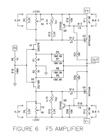
R10 and R7 in Figure 5 are the input resitors to gnd, those are the 47.5K in the F5 schematic. So, at the moment i just placed the 12Ohm resistor in series with R12, and not as it should be?
But, I think i cant put the resistor at the right spot with my PCBs (V3 of the diy audiostore) ?

R10 and R7 in Figure 5 are the input resitors to gnd, those are the 47.5K in the F5 schematic. So, at the moment i just placed the 12Ohm resistor in series with R12, and not as it should be?
But, I think i cant put the resistor at the right spot with my PCBs (V3 of the diy audiostore) ?

15283 is correct.
It show the big node split into two sections. The Signal Return on the left side and the Main Audio Ground on the right side.
Then the HBRR joins the two parts together.
Post15284 showing the extra resistor in the signal route is wrong.
It does not attenuate the hum in the input circuit loop.
Can you show a pic of the PCB traces in the area where decoupling ground, PSU Zero Volts and Speaker Return are coming together?
Last edited:
So I took the photos, and with a knife I think its not that hard to remove the connection from the pcb... (although I am really unhappy that I have to do that)
there is a line between input GND and the output gnd, there I will put the resistor, right?


there is a line between input GND and the output gnd, there I will put the resistor, right?
Check that the input circuit is still complete if you cut that trace.
Remember the two input pads to IN and IN gnd are both signals. Both signals must continue into the circuit.
Remember the two input pads to IN and IN gnd are both signals. Both signals must continue into the circuit.
ok, i will check.
Whats with the ground between R3/R4 in the schematic of the F5, so i mean the mass thats in between the 2SK170 and 2SJ74. Is that a InGND or the PSU-GND/Speaker-GND?
Whats with the ground between R3/R4 in the schematic of the F5, so i mean the mass thats in between the 2SK170 and 2SJ74. Is that a InGND or the PSU-GND/Speaker-GND?
is there a link you can post so we can see the traces you are referring to?
Attachments
Last edited:
🙁🙁🙁 ok maybe its not that easy. Due to all the cables i tried to draw the pcb connections. When i remove that connection I was thinking about and add the HBRR, then there is no connection between R2 and In-GND anymore. Thus I have to unsolder R2 and put it as in the drawing?

here a photo, and in green the connection that would be wrong then.

The question I was asking before refers to this schematic:

Do i need option A or B?
here a photo, and in green the connection that would be wrong then.
The question I was asking before refers to this schematic:
Do i need option A or B?
Attachments
Sry, I just saw now that you added a schematic as well, I just have an older version I think, so some different names (the schematic I used matches the values on the PCB)
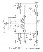
I posted the first watt version.
it is the original.
Now I see R3/4 in their new locations.
The Power ground/decoupling ground/speaker return are all on the Main Audio Ground.
The Signal Return is separate.
The green arrow to B looks better. It takes the feedback from the speaker output back into the MAG
This is an example of using gnd for all points that are actually doing different duties. We were discussing this elsewhere.
Last edited:
soo, I applied the changes on one channel.
Similar as before, I can now already hear a hum when I connect only channel with the preamp. (not as without the 12Ohm resistor only when i connect both channels with the preamp)
I will now also add the resistor in the other channel, but I don't have a lot of hope... :/
Similar as before, I can now already hear a hum when I connect only channel with the preamp. (not as without the 12Ohm resistor only when i connect both channels with the preamp)
I will now also add the resistor in the other channel, but I don't have a lot of hope... :/
yep, still a hum. When i connect one channel with the preamp I can hear it, it doesn't depend on the side.
It's really weird, as I did not observe this behavior without the hum breaking resistors? When I connected only one channel the amp was totally silent. Only when I connected the second one I had the loop, thus a hum...
Could it be, that the source of the hum comes from somewhere else? One thing that is still in my mind is, that the DCB1 analogue GND has no connection to earth/case. This is normally done that way. But i still can't see the impact to the cross channel hum I had😕😕😕
So, I also tried 82 Ohms.
When its in one channel: I connect one input (the one with the hum breaking resistor) with preamp: i can hear a really loud hum on this side of the speaker. When i also connect the other input with the preamp the hum on first side gets a little bit more quiet but it is still louder then without any resistor. A little bit surprising is that the speaker without the hum breaking resistor is totally quiet.
With a resistor in both channels: I hear a hum when i connect the first input. when i connect also the second one i hear a hum in both speakers.
I also tried with a different preamp, the same effect, so I still think its the cross channel ground loop. Maybe the resistor is still at the wrong position? I am not sure, don't know what to do 🙁
So, I also tried 82 Ohms.
When its in one channel: I connect one input (the one with the hum breaking resistor) with preamp: i can hear a really loud hum on this side of the speaker. When i also connect the other input with the preamp the hum on first side gets a little bit more quiet but it is still louder then without any resistor. A little bit surprising is that the speaker without the hum breaking resistor is totally quiet.
With a resistor in both channels: I hear a hum when i connect the first input. when i connect also the second one i hear a hum in both speakers.
I also tried with a different preamp, the same effect, so I still think its the cross channel ground loop. Maybe the resistor is still at the wrong position? I am not sure, don't know what to do 🙁
Look at your internal grounding. Are you using a * star ground system? Every ground wire should go to one spot inside the amp. No matter how short the distance each ground wire needs to be a home run. That star point is where the bridge rectifier or thermistor is connecting to chassis ground. It is the only place the chassis is grounded.
When you first connected the preamp and have a hum on one channel, before the resistor(s) were added, I thought it was a simple ground loop, from one piece of equipment to another. But this appears to be an internal grounding issue.
There is no need to cut traces on a board that everyone has used with no hum.
Keep looking. I have had to reground an amp in the past because I couldn't get it through my thick head that even a short run needed to be a home run. This includes speaker grounding to * star point.
Hope this helps,
Rush
go back a stage.So, I also tried 82 Ohms.
When its in one channel: I connect one input (the one with the hum breaking resistor) with preamp: i can hear a really loud hum on this side of the speaker. When i also connect the other input with the preamp the hum on first side gets a little bit more quiet but it is still louder then without any resistor. A little bit surprising is that the speaker without the hum breaking resistor is totally quiet.
With a resistor in both channels: I hear a hum when i connect the first input. when i connect also the second one i hear a hum in both speakers.
I also tried with a different preamp, the same effect, so I still think its the cross channel ground loop. Maybe the resistor is still at the wrong position? I am not sure, don't know what to do 🙁
Insert zero ohm dummy plugs into the inputs. Measure the Hum+Noise (on the 199.9mVac setting) at the output and the output offset . Report your results.
Look at your internal grounding. Are you using a * star ground system? Every ground wire should go to one spot inside the amp. No matter how short the distance each ground wire needs to be a home run. That star point is where the bridge rectifier or thermistor is connecting to chassis ground. It is the only place the chassis is grounded.
When you first connected the preamp and have a hum on one channel, before the resistor(s) were added, I thought it was a simple ground loop, from one piece of equipment to another. But this appears to be an internal grounding issue.
There is no need to cut traces on a board that everyone has used with no hum.
Keep looking. I have had to reground an amp in the past because I couldn't get it through my thick head that even a short run needed to be a home run. This includes speaker grounding to * star point.
Hope this helps,
Rush
Yes, I use a * ground. Its the GND of the PSU board. from there only one connection goes to the case with a CL60 in series. I just removed this connection and tested if there is a connection from the star ground to the case -> nothing (whats good I think 😉)
I will try that!please try to remove the main filter(230v)
go back a stage.
Insert zero ohm dummy plugs into the inputs. Measure the Hum+Noise (on the 199.9mVac setting) at the output and the output offset . Report your results.
I do this again with zero HBRR and HBRL, right? so just put the input signal to GND and measure the output?
go back a stage.
Insert zero ohm dummy plugs into the inputs. Measure the Hum+Noise (on the 199.9mVac setting) at the output and the output offset . Report your results.
Ok, so with input connected to gnd, I measure 0.0mVac on both channels, 5 and 2 mV offset 😕😕
the same results with speaker connected. (and I can't hear any hum)
- Home
- Amplifiers
- Pass Labs
- F5 power amplifier