ZM- Wait, are you trying to tell me the scratchy woosh sound I hear when adjusting vol/bal is not desirable? 😉
I built the kit straight, aside from some cosmetic flourishes. Eventually I'll build a new chassis, putting the controls and connectors in the proper locations, at which point I'll replace the pots (possibly ditching the balance control altogether). This will come after the ACA, and possibly speakers. When the time comes I'll post any Qs to the appropriate forum.
I built the kit straight, aside from some cosmetic flourishes. Eventually I'll build a new chassis, putting the controls and connectors in the proper locations, at which point I'll replace the pots (possibly ditching the balance control altogether). This will come after the ACA, and possibly speakers. When the time comes I'll post any Qs to the appropriate forum.
Just an update regarding my F5 build that everyone has been so helpful with. I ordered the matched JFETs from Spencer per Patrick's recommendation (~$40). Not $20, but better than ordering the LSs w/no guarantee of two closely matched pairs.
In the meantime I've finished the chassis, so hopefully after the JFETs arrive I'll be able to pop them into the boards and set the bias without too much drama. After that, I'll post some pretty pics. 🙂
Like I said earlier, this amp is for my son. I got a Bottlehead Smash preamp kit for Christmas, which I finished last night. That'll drive the F5 until I build my Amp Camp monoblocks, at which point he'll have to go back to using is AMC hybrid preamp, or build his own pre.
OK, one teaser photo, attached 😉
Wow! You certainly teased me...😀
Is that done with frontpanel express?
Love to see the pictures soon...
Walter
Wow! You certainly teased me...😀
Is that done with frontpanel express?
Love to see the pictures soon...
Walter
Sketchup, jigsaw, files. 🙂
+1...and dangerous worship at that if I start thinking about giving in a try myself. But then I look at an Ikea bookshelf (permanent, purpose-kept reminder of my clumsiness), reason kicks in, I picture bent metal and scraped skin and I whip out my card to have someone else take care of things 😀
I was dreading cutting out the logo myself. Then the jigsaw cut straighter and smoother than I expected, and the amount of filing needed was minimal. I wasn't watching the clock, but I think I got it done in less than an hour.
I'll add P3 and thermistors myself, everything is on hand. Just needed to sort which part goes where and with the guidance provided (thanks!) I'm a big step closer 🙂
Monitor the bias when you adjust P3. I blow up an amp because I didn't know it affected the bias. Dont be like me. 😉
I have used my F5 For a while with no problems. Today the R12 resistor turned red hot and into smoke in one channel when I started up the amp.Anybody know what might cause this?
pull out all semis and check them
obviously, replace R12 , check all others
check for metal debris on heatsink , prior to putting mosfets back
be sure that you torque them properly on hsink
don't use overly thick mica and , yes , mica & goo is better than gray silicone thingie
obviously, replace R12 , check all others
check for metal debris on heatsink , prior to putting mosfets back
be sure that you torque them properly on hsink
don't use overly thick mica and , yes , mica & goo is better than gray silicone thingie
I'm just another newbie, fascinated by the simple design of the f5, and I decided to build it as my second project after 10 years of abcense from amp building.
All parts are already on hand, but since I will build up the amp standing vertically I'm wondering where to place all the parts in thermal issues.
CAD Construction of the amp:
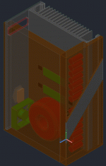
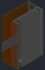
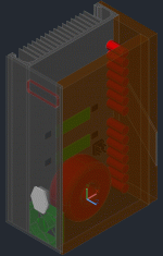
Best placement of Caps, Amps, trafo and vent are not clear to me.
Could you support me by giving an idea which one will be the best compromise for all parts?
I'm trying to keep the temp of the Caps low while putting the pcb on the best place to dissipate the heat.
On the other hand I want to put the transformer as low as possible.
Side view:
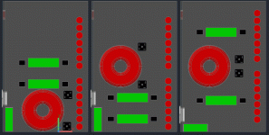
Any ideas welcome 🙂
Thanks in advance!
All parts are already on hand, but since I will build up the amp standing vertically I'm wondering where to place all the parts in thermal issues.
CAD Construction of the amp:


Best placement of Caps, Amps, trafo and vent are not clear to me.
Could you support me by giving an idea which one will be the best compromise for all parts?
I'm trying to keep the temp of the Caps low while putting the pcb on the best place to dissipate the heat.
On the other hand I want to put the transformer as low as possible.
Side view:

Any ideas welcome 🙂
Thanks in advance!
mosfets - try to situate them at horizontal line drawn on 1/3 of heatsink height
xformer - as far apart of pcb as you can
rest ....... wherever is left 😉
xformer - as far apart of pcb as you can
rest ....... wherever is left 😉
mosfets - try to situate them at horizontal line drawn on 1/3 of heatsink height
xformer - as far apart of pcb as you can
rest ....... wherever is left 😉
xformer - as far apart of pcb as you can
rest ....... wherever is left 😉
Thank you, Zen Mod.
Both pcbs doesn't fit in one line, how much vertical distance should I keep between them?
Size of the heat sink is 270 x 430 mm
I would suggest 100 and 200mm off the ground, is this ok? Or should I put it more upwards with more distance to each other?
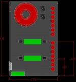
Thanks for your patience with an noob 🙄
Both pcbs doesn't fit in one line, how much vertical distance should I keep between them?
Size of the heat sink is 270 x 430 mm
I would suggest 100 and 200mm off the ground, is this ok? Or should I put it more upwards with more distance to each other?

Thanks for your patience with an noob 🙄
The original F5 design showed 1K +100K input impedance. Later this was changed to 4.7K+ 47K. Recently at a DAC comparison a similar setup (dac/preamp) to mine sounded dread-full, which we contributed to the fact that the tube-amp in use at that day had a 12K input impedance. The suspicion being that this low input impedance was the cullpit.
My question is what the advantage/disadvantage of using the +/-50K or 100K input impedance and why was the change made to the original design?
My question is what the advantage/disadvantage of using the +/-50K or 100K input impedance and why was the change made to the original design?
I would suggest 100 and 200mm off the ground, is this ok? Or should I put it more upwards with more distance to each other?
Here's a similar build: http://www.diyaudio.com/forums/pass-labs/121228-f5-power-amplifier-280.html#post1740775
- Home
- Amplifiers
- Pass Labs
- F5 power amplifier

