F5 amplifier has a gain of 5.5 so 2volts rms source signal multiplies with 5.5 and it makes about 11volts rms.F5 gives about 15volts rms max.So you can not get F5's max power with many sources without preamp(voltage gain)
So, maximum voltage before clipping is 15v rms/5.5=2.72V RMS?
starting F5
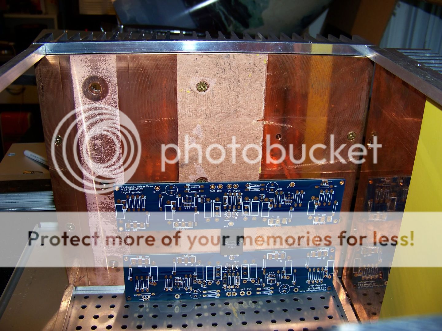
I'm trying to get two cviller boards on this heatsink. Anyone here know if this will get too hot with standard bias settings? Measurements are around 10 by 9 by 1 3/4" and the copper heat spreader is about 1/4" thick. I am planning on populating the inners on the top and the outers on the bottom for a 4 channel amp. This picture would indicate just the left channel for instance.
Thanks,
Everett
I'm not exactly sure what 8off means, but I assume it means 8x or something like that. In that case, no there would only be 4 boards in this chassis. I read your post about heat sinks and it sounds like there will probably be too much heat, but I don't know how much heat my sinks can dissipate since they're salvaged. I have also not seen heat spreaders on commercial sinks, so it's hard to compare. All I can go by is dimensions, so hopefully someone else is more knowledgeable in this area.
I'm not exactly sure what 8off means, but I assume it means 8x or something like that. In that case, no there would only be 4 boards in this chassis. I read your post about heat sinks and it sounds like there will probably be too much heat, but I don't know how much heat my sinks can dissipate since they're salvaged. I have also not seen heat spreaders on commercial sinks, so it's hard to compare. All I can go by is dimensions, so hopefully someone else is more knowledgeable in this area.
Nice copper spreader! 😀
Two channels on a 10x9 heat sink might leave you with a very hot
 amp. Are you running it balanced? If so, you could lower the supply voltage a bit.
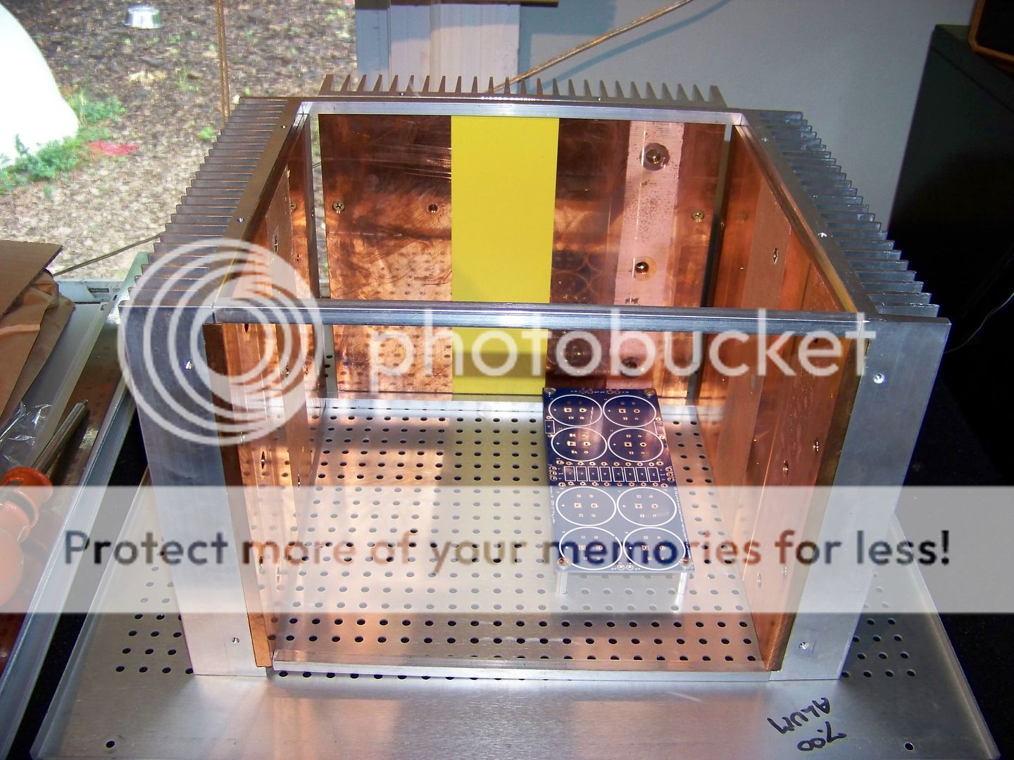
Thanks Christian, I see that my second set of boards shipped too. Here's what I have going so far. Just a mock up, but I think it will look pretty nice once I get it all populated. I'll probably end up doing one board per side and use the back sink for rectifier diodes. I have never built a class A amp, so it's hard for me to imagine such a large amount of heat coming from two MOSFETs. I guess I can always add a channel if I find that it runs cooler than expected.
could you confirm the size of each of those heatsinks and the thickness of the backplate.
They look big enough to do one channel of F5.
Why do you want to strap two channels on?
The copper spreader might not be required, if that backplate is thick enough alone.
They look big enough to do one channel of F5.
Why do you want to strap two channels on?
The copper spreader might not be required, if that backplate is thick enough alone.
I think the backplate is only 1/16" or so because they (sorry can't take the credit) milled the copper into the aluminum. The copper is more like 5/16" upon further inspection making a total plate of 3/8". I plugged all the dims into the ESP heatsink spreadsheet and got 0.65 deg C/W. I guess I just wanted more outputs for this giant footprint, but I'm probably going to end up splitting the boards into two amps, otherwise I may end up with a (not so) portable space heater 🙂
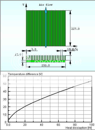
I found another interesting link in case someone wants some very indepth reading on heatsinks.
I found another interesting link in case someone wants some very indepth reading on heatsinks.
There is a free download that allows modeling of any shape heatsink with single or multiple devices of any size to be located any where.
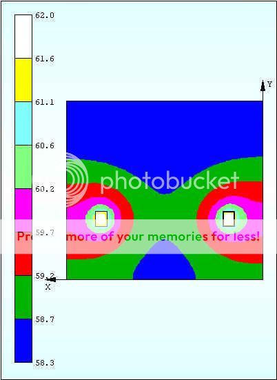
Great for finding the optimum locations for minimum Tc for all devices.
I can't recall the website, but it is associated with a commercial operation.
With the thin remaining backplate, the copper spreader is definately required.
I see milling marks on the copper. If the other side looks similar then all these must be ground off to allow intimate contact between the aluminium and the copper. Similarly for the aluminium. You want the maximum area of metal to metal contact at the interface. Any and all gaps must be filled with thermal compound. You will need a lot more screws to clamp the plates together, to ensure that metal to metal contact, to the point of buckling the plates where there are bigger gaps.
Beware, the coefficient of expansion for copper and aluminum are different.
This thing may get hot enough to cause bending due to this...
This thing may get hot enough to cause bending due to this...
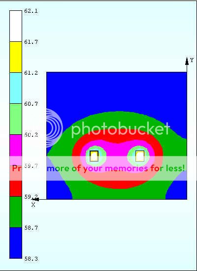
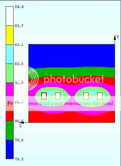
Here are some images from the above tool. What a great piece of software for a diy guy! The heat layouts are based on the cviller board spacing and a generic 16x20mm footprint dissipating 30W.
Yes, that is familiar.
adjust until the contact interface uner the device/s is at it's coolest
adjust until the contact interface uner the device/s is at it's coolest
Would there be any gain to using separate supplies per channel i.e +- 68000uf or a single supply of +- 136000uf with the anti ripple resistors? between the caps
With a double supply ("monobloc" or "dual mono") the inter channel isolation is 100%.
With a single supply ("stereo") there is some interchannel "cross-talk" via the supply.
We're assuming in the second case there are two, not one power transformers??
In practice it may not make a real world difference to your ears - or it might.
Certainly opens up different chassis variations.
_-_-bear
Hi.I have 600va transformer and it has 4x18v output.And i use them seperately.2x18v for one channel and other 2x18v for another channel.Is not it enough to deny crosstalking?I think it is not same as two transformer?Does it make big difference?
Should be fine umut... especially for a Class A design where the current draw is fairly constant...
the core, the primary and the chassis are common between the two channels. That can never have as good separation as two monoblocks.Hi.I have 600va transformer and it has 4x18v output.And i use them seperately.2x18v for one channel and other 2x18v for another channel.Is not it enough to deny crosstalking?I think it is not same as two transformer?Does it make big difference?
But, 4 isolated secondaries is a very big improvement on a shared set of secondaries.
Thanks for the response Bear. Yes I was intending to use two transformers in the one chassis with 4 bridge rectifiers. What would be the size of trannies to use as Nelson I understand uses a 300VA in the Firstwatt F5? Would two 300VA's be overkill?
- Home
- Amplifiers
- Pass Labs
- F5 power amplifier