
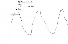
Hi. I remember that P(RMS)=(V(RMS) )^2 /R makes 54/8 =6.75 watt class A RMS power when applying sinusoidal signal(when bias is 1.3A )the peak of signal( pure class A) is about 10.3 volts and RMS of it is about 7.35 volts. Am i wrong? 😕
Attachments
Last edited:
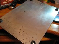
Dear osscar,The bottom plate is almost ready...with ventilation holes.
are you sure your housing is enough airy?
To me, the road from hell to outwards should be as wide as possible... 😉
Cheers!
Hi. I remember that P(RMS)=(V(RMS) )^2 /R makes 54/8 =6.75 watt class A RMS power when applying sinusoidal signal(when bias is 1.3A )the peak of signal( pure class A) is about 10.3 volts and RMS of it is about 7.35 volts.
Am i wrong? 😕
Yes you are.
V(RMS)^2 is not 54
pls read carrefully 🙂
OK, one more time, extensively:
Vout (peak) for Nelson's standard edition F5 is roughly 20V
That makes 14.18V RMS
14.18V squared is 201.2
201.2 divided by 8 (speaker impedance) is 25W (RMS)
The point is that you get RMS value by dividing with 1.41 (square root of 2) - or by multiplying by 0.707.
Dividing peak value by 2 gives you average value (for sinusoidal signal), not RMS.
😉
I was recently corrected on this, so now that I have been enlightened, I will share the facts.
Prms = Ppk/1.414 = Vpk^2/(1.414xR)
Pavg = Ppk/2 = Vpk^2/(2xR)
Pavg does not equal Prms. Apparently a lot of physicists believe Prms is a misnomer, and we should be using Pavg which is Vrms^2/R or Vpk^2/(2xR).
Prms = Ppk/1.414 = Vpk^2/(1.414xR)
Pavg = Ppk/2 = Vpk^2/(2xR)
Pavg does not equal Prms. Apparently a lot of physicists believe Prms is a misnomer, and we should be using Pavg which is Vrms^2/R or Vpk^2/(2xR).
Last edited:
OK, one more time, extensively:
Vout (peak) for Nelson's standard edition F5 is roughly 20V
That makes 14.18V RMS
14.18V squared is 201.2
201.2 divided by 8 (speaker impedance) is 25W (RMS)
The point is that you get RMS value by dividing with 1.41 (square root of 2) - or by multiplying by 0.707.
Dividing peak value by 2 gives you average value (for sinusoidal signal), not RMS.
😉
I was recently corrected on this, so now that I have been enlightened, I will share the facts.
Prms = Ppk/1.414 = Vpk^2/(1.414xR)
Pavg = Ppk/2 = Vpk^2/(2xR)
Pavg does not equal Prms. Apparently a lot of physicists believe Prms is a misnomer, and we should be using Pavg which is Vrms^2/R or Vpk^2/(2xR).
Prms=(Vpk/1.414)^2/R
=(Vpk/sqrt 2)^2/R
=(Vpk^2/2)/R
=Vpk^2/(2*R)
=(Vpk^2/R)/2
=(Vpk^2/2)/R
Prms=(Ipk/1.414)^2*R
=(Ipk/sq rt 2)^2*R
=(Ipk^2/2)*R
=(Ipk^2*R)/2

They are the formulas for average power.
"In common use, the terms "RMS power" or "watts RMS" are erroneously used to describe average power." Wikipedia
Check the link below. Feel free to edit the wiki page if it is in error.
Audio power - Wikipedia, the free encyclopedia
Here is one more quote:
"The RMS value of power is not the equivalent heating power and, in fact, it doesn’t represent any useful physical quantity. The RMS and average values of nearly all waveforms are different. A notable exception is a steady DC waveform (of constant value), for which the average, RMS, and peak values are all the same.
It should be noted that the term “RMS power” is (mis)used in the consumer audio industry. In that context, it means the average power when reproducing a single tone, but it’s not actually the RMS value of the power." Roy Lewallen
Last edited:
Hi. I remember that P(RMS)=(V(RMS) )^2 /R makes 54/8 =6.75 watt class A RMS power when applying sinusoidal signal(when bias is 1.3A )the peak of signal( pure class A) is about 10.3 volts and RMS of it is about 7.35 volts. Am i wrong? 😕
so I think i am right 🙂
How did you get 54?
For push pull circuit, class A current = 2 x bias current = 2 x 1.3 = 2.6A
For push pull circuit, class A current = 2 x bias current = 2 x 1.3 = 2.6A
Last edited:
Backwards, or same thing ?
From my adequate experience I know what to expect from 25Vdc rails +/-
At least I think I do, or maybe just roughly
All I need to know is the needed bias not to leave classA, or when it does
And I trust Nelson to know, right
When in doubt, you get a clear "I dont know"
btw, are we forgetting the needed input voltage to get the full output ?
Well, its a variable
Last edited:
...Dividing peak value by 2 gives you average value (for sinusoidal signal), not RMS.
😉

The(y are) the formula(s) for average power.
...[/B]" Roy Lewallen
Well, yeah Manual does say 54watt peak, average of 27watt classA into 8ohm
"Average" seems a bit misguiding word to me, if you take it literally
The old story of the "actual watt"(continious?), and the somewhat misused "music watt", right
"Average" seems a bit misguiding word to me, if you take it literally
The old story of the "actual watt"(continious?), and the somewhat misused "music watt", right
Last edited:
Hi. I remember that P(RMS)=(V(RMS) )^2 /R makes 54/8 =6.75 watt class A RMS power when applying sinusoidal signal(when bias is 1.3A )the peak of signal( pure class A) is about 10.3 volts and RMS of it is about 7.35 volts. Am i wrong? 😕
I was referring to umut1001 not Manual
Ok but I did not understand that why we are X2 the bias. P channel has positive output and n channel transistor has negative output.I calculate them seperately.and on positive side it is 10 volts Peak(in class a mode)and it makes 7 volts RMS voltage.Can someone show it in a picture ?
sinewave Pavg = Vpk^2/R/2 = Vrms^2/R = Ipk^2*R /2 = Irms*R = Ipk*Vpk/2 = Irms*Vrms.
we have variables of P, R, Irms, Ipk, Vrms, Vpk, R. Choose the formula that has just one unknown and solve for the unknown.
In the F5 we know bias current (Ib), Ipk=2*Ib, we know the load (R).
we want Power, that is the unknown. Choose P=Ipk^2*R/2 = 2.6^2*8/2=27.04W of average power when the signal is a sinewave.
current bias maximum minimum
.................................................................................................
Upper half: 1.3 . 2.6 A . 0 A
...................................................................................................
Lower half: 1.3 . 0 A . 2.6 A
.................................................................................................
Upper half: 1.3 . 2.6 A . 0 A
...................................................................................................
Lower half: 1.3 . 0 A . 2.6 A
Attachments
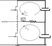
A PP amp can be seen as a bridge: the load sees the difference between the upper and lower halves currents.
Last edited:
and the difference between the upper half and lower half currents at any instantaneous moment must flow through the load and the NFB if any.
If the upper and lower currents are 1.3A then the difference is zero Amperes and nothing flows to the load and nothing flows through the NFB.
If the upper current drops to 1A and the lower current increases to 1.6A, the difference (-0.6A) must flow from the load and from the NFB to the lower supply rail.
similarly if the decrease and increase were 1.2A then the upper would pass 0.1A and the lower would pass 2.5A and the load +NFB would pass 2.4Apk at that moment.
Note, here we have a ClassA amplifier operating in ClassA and the supply currents are changing from 0.1A to 2.5A. The supply rail currents are NOT constant, despite what many wrongly assume/state.
- Home
- Amplifiers
- Pass Labs
- F5 power amplifier