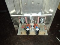
After that I have boxed my F5, I noticed a problem.
When I set the offset at about -2/+2 mV without the cover, it rises at 30/40 mV after 10 minutes that i put on the cover. Again, if I take off the cover, the offset falls to 0.
Does the jfets need an heatsink for a better stability of the offset, or the problem comes from elsewhere?
Regards
When I set the offset at about -2/+2 mV without the cover, it rises at 30/40 mV after 10 minutes that i put on the cover. Again, if I take off the cover, the offset falls to 0.
Does the jfets need an heatsink for a better stability of the offset, or the problem comes from elsewhere?
Regards
After that I have boxed my F5, I noticed a problem.
When I set the offset at about -2/+2 mV without the cover, it rises at 30/40 mV after 10 minutes that i put on the cover. Again, if I take off the cover, the offset falls to 0.
Does the jfets need an heatsink for a better stability of the offset, or the problem comes from elsewhere?
Regards
No, you have just discovered for yourself the reason why Papa suggests we do the adjustments with the cover on.

Hello everyone,
I would like to know how to figure out what value resistor I would replace the 100ohm ones used to set feedback to lower the gain. I would like to lower the gain to work well with a 6sn7 based Aikido preamp which should be about 20db, I think. The sources are 1.5v and 2v. The speaker efficiency is 90db/w. I am affraid I will have too much gain. Should I just use a F4?
I would like to know how to figure out what value resistor I would replace the 100ohm ones used to set feedback to lower the gain. I would like to lower the gain to work well with a 6sn7 based Aikido preamp which should be about 20db, I think. The sources are 1.5v and 2v. The speaker efficiency is 90db/w. I am affraid I will have too much gain. Should I just use a F4?
With the cover ON 😱
How to do it?
Trial and error...

You can try to adjust slightly below 0mv (say -10mV) put the cover on and see if it goes above 0 with the cover on and the redo and redo and redo...
No reason to screw the lid on while doing this though. 😉
I would set it around the inverse of the offset after putting the cover on.
So for a 40mV offset, I would adjust to -40mV and put the cover on again, check after an hour, and adjust again.
Which brings me to my question: my F5 will be running in free air. I assume this high sensitivity to temperature will create problems with wildly fluctuating offset - should I think about additional protection?
Last edited:
I have been listening to F3 for a while,but switched to F5 yesterday,and I must say I was surprised by the detalies it plays....
I would set it around the inverse of the offset after putting the cover on.
So for a 40mV offset, I would adjust to -40mV and put the cover on again, check after an hour, and adjust again.
Which brings me to my question: my F5 will be running in free air. I assume this high sensitivity to temperature will create problems with wildly fluctuating offset - should I think about additional protection?
You can do what I do, which is to mount the thermistors
on the devices. Also, the exact values of the thermistors
and/or the resistors in series with them will vary by
device number, as the coefficients of different Mosfets
can vary quite a bit.
I usually correct in halves. In the case you cite, I would
set the cold offset to -20 mV
😎
I usually correct in halves. In the case you cite, I would
set the cold offset to -20 mV
😎
aaahhhhaaaa said Mr. Moto. "Kimono go up little bit at a time...keep client interested."
Thanks again, Mr. Pass. I will be building this winter for sure - we are currently seeing room temps of 35 degrees C, so a Class A is kind of out of the question!
another one alive
Hi,
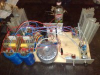
last weekend I fired the f5 proto. The first to use the proto testbed, getting a cheap trannie made this go in to higher gear. I'll be mounting some fans to the heatsinks to allow higher dissipation and thus try stuff like the alephJ and other First watt designs. Guess I'll be working backwards.
I really like the uniform psu and cooling format used by mr Pass. This way I can use whatever I have already and try out different designs rather easy and inexpensive. Something I really like!
below some pic's
regards,
Joris
Hi,
last weekend I fired the f5 proto. The first to use the proto testbed, getting a cheap trannie made this go in to higher gear. I'll be mounting some fans to the heatsinks to allow higher dissipation and thus try stuff like the alephJ and other First watt designs. Guess I'll be working backwards.
I really like the uniform psu and cooling format used by mr Pass. This way I can use whatever I have already and try out different designs rather easy and inexpensive. Something I really like!
below some pic's
regards,
Joris
Attachments
try rotating the amp PCBs to the vertical and fit the output devices direct to the back of the heatsink without needing the intervening clamp plate.
The devices will run cooler and the sink will run slightly hotter.
The devices will run cooler and the sink will run slightly hotter.
Hi Andrew,
Thanks for the suggestion. I know the thermal resistance will decrease when using your method. However, this way I can still mount other designs above the F5 using a similar construction. This makes it easier to compare designs (the main reason I used faston clips and such). Just switch off, swap leads and switch on again...
The testbed is not meant for ultimate sound quality or perfect cicuit parameters. Just to get to grips with a design (adjustment etc) and an initial impression of the sound. Cooling just needs to be sufficient to not blow the fets/transistors most of the time.
Anyway, thanks and I'll remember when building the final design of choice.
regards,
Joris
🙂
Power Supply Caps
Has anyone had any experience with these power supply caps?
http://www.bgmicro.com/index.asp?PageAction=VIEWPROD&ProdID=12875
That's a lot of capacitance for $10.
Thanks,
Steve
Has anyone had any experience with these power supply caps?
http://www.bgmicro.com/index.asp?PageAction=VIEWPROD&ProdID=12875
That's a lot of capacitance for $10.
Thanks,
Steve
Power Supply Caps
$40 bucks is ok. But, I usually do eveything in dual mono. So, it would be $80. But then, that is one hell of a lot of capacitance for these amps.
$40 bucks is ok. But, I usually do eveything in dual mono. So, it would be $80. But then, that is one hell of a lot of capacitance for these amps.
Power Supply
2 questions (one specifically for Andrew T):
1. Hey Andrew, if I built a power supply with a 600VA transformer and used 4 of the above mentioned caps to give 272,000 uF total (136,000 per rail), I would assume that you would recommend using a thermistor in the primary as well as the secondary of the transformer -- as per your post 3008. If that is in fact the case, what resistance would you suggest for the thermistor in the secondary of the transformer?
2. I like the idea of having the power supply seperate so that I can easily try out future amps without building up power supplies each time. It is for that reason that I'm thinking of placing the power supply in its own enclosure seperate from the amplifier modules. Is there any particular length of the umbilical that I sould not exceed?
Thanks,
Steve
- Home
- Amplifiers
- Pass Labs
- F5 power amplifier