so In order to prevent hum from ground loops
how you will suggest to connect that pcb to PSU and Input rca /output binding post
how you will suggest to connect that pcb to PSU and Input rca /output binding post
One wire from PCB to star ground
One wire from black binding post to star ground
Use shielded wire from RCA to PCB (shielding goes to PCB too)
RCA must be insulated from chassis.
That's it.
One wire from black binding post to star ground
Use shielded wire from RCA to PCB (shielding goes to PCB too)
RCA must be insulated from chassis.
That's it.
I am contemplating to build an Xed version of th F5 . Post#3644
I had a quick reading again of the whole thread.
It seems to me that an X version is not possible because this topology needs differential inputs. Am i right?
bobodioulasso said:One wire from PCB to star ground
One wire from black binding post to star ground
Use shielded wire from RCA to PCB (shielding goes to PCB too)
RCA must be insulated from chassis.
That's it.
thx
samoloko said:stein2 can you post a closer picture of your PSU - I would like to know how are you did gnd wiring
with so much capacitance how you are starting up - with soft start or cl-60 what value fuse you use
Sorry for the delay in response, I was away for almost a week on a business trip.
Now I'm back, and a question for you, do you mean my first attempt with wired connections or the new project with the PSU made on PCBs?
As for starting, there's a thermistor from a PC PSU, 10 Ohms NTC in series with the 230V/50Hz primer and a 0.1uF/250V capacitor taken from the contacts of the IEC connector from the same PC PSU connected in parallel with the primer of a 400VA transformer...
If you need a picture showing the PCB, I'll make a few, and if the older wired solution is what you want to see, I'll look for an image showing the details. In both cases there's no issue with hum, ground loop or any audible noise...
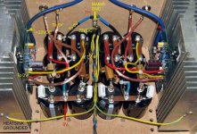
Bit too late to edit previous post. Here's an image how I did it without a printed board.
To the "0V" point goes the center tap from the transformer if one rectifier bridge is to be used, and I grounded the heatsinks because the "box" was made of MDF, not metal. In case that the housing is of metal, do not ground the heatsinks with anything, unless they are electrically insulated from the metal of the housing which will be grounded anyway.
To the "0V" point goes the center tap from the transformer if one rectifier bridge is to be used, and I grounded the heatsinks because the "box" was made of MDF, not metal. In case that the housing is of metal, do not ground the heatsinks with anything, unless they are electrically insulated from the metal of the housing which will be grounded anyway.
Attachments
samoloko said:thx for response stein2
If It Is not a problem for you you can post a shot from your new F5
Bottom...
Attachments


heh I had a bit of bad luck in helping a friend bring up a F5. He wasn't sure about the FQA devices and where they went, and said he used the locations on Jack's website. I figured that was right, so I decided to double-check the AudioExpress article and happened to read the paragraph in the "Parts Selection" that said Q3 is N-channel and Q4 was P-channel... so, it jived with Jacks website, so I figured... it must be right.... WRONG 😱
Anyways, I first tried a 2.5A slo blo and then tried a 3.0A slo blo .. anyways, just blew the fuse both times. So, given what I did, are there any parts I should check? Voltage on the PSU rose like 5-6V then the fuse blew... I figured I could check the parts, but figured I'd be lazy and ask around 😎
Anyways, I first tried a 2.5A slo blo and then tried a 3.0A slo blo
.. anyways, just blew the fuse both times. So, given what I did, are there any parts I should check? Voltage on the PSU rose like 5-6V then the fuse blew... I figured I could check the parts, but figured I'd be lazy and ask around 😎luvdunhill said:........ I'd be lazy and ask around 😎
PchannelonPositivesideofPsu
NchannelonNegativesideofNsu

luvdunhill said:heh I had a bit of bad luck in helping a friend bring up a F5. He wasn't sure about the FQA devices and where they went, and said he used the locations on Jack's website. I figured that was right, so I decided to double-check the AudioExpress article and happened to read the paragraph in the "Parts Selection" that said Q3 is N-channel and Q4 was P-channel... so, it jived with Jacks website, so I figured... it must be right.... WRONG 😱
Anyways, I first tried a 2.5A slo blo and then tried a 3.0A slo blo
Luvdunhill,
I did the same thing out of sheer blindness and lack of double checking, brought it up only a few volts on the variac, but the bias was all weird compared to the other channel. I just swapped them and it ran fine.
Originally posted by Tea-Bag lack of double checking
I double checked and was still wrong
 Main problem was I turned my brain off
  Anyways, I had it at full current, so I'm hoping things are okay. No smoke / smells / sounds / etc.
That is why you should have a lab PSU with variable current limit to test power amps.
😉
Patrick
😉
Patrick
EUVL said:That is why you should have a lab PSU with variable current limit to test power amps.
😉
Patrick
My variac usually starts shaking and doing it's dance if I shorted something. Considered an early warning sign I guess.
well, things are looking much nicer now 😀
So, what kind of bias would you recommend for this load:
So, what kind of bias would you recommend for this load:
An externally hosted image should be here but it was not working when we last tested it.
luvdunhill said:heh I had a bit of bad luck in helping a friend bring up a F5. He wasn't sure about the FQA devices and where they went, and said he used the locations on Jack's website. I figured that was right, so I decided to double-check the AudioExpress article and happened to read the paragraph in the "Parts Selection" that said Q3 is N-channel and Q4 was P-channel... so, it jived with Jacks website, so I figured... it must be right.... WRONG 😱
Reminds me of the line in Young Frankenstein: "Change negative to positive and minus to plus..."
Hmm, I thought folks would look at the schematic. I did Nelson's schematic in Multisim and transferred it to Ultiboard when I did my boards, but didn't bother to change the reference designators since I did them without a silk screen. I've never blown up an F5.
I'll change the identifiers anyway.
Pretty soon there won't be anymore F5's unless Panasonic starts to make the P-Channel JFETs.
jackinnj said:
Pretty soon there won't be anymore F5's unless Panasonic starts to make the P-Channel JFETs.
Panasonic _does make P-Channel jfets: the 2sj0164 (alongside its complementary N-Channel part, the 2sk1104). With a max IDss of only -6mA though (top end of the "R" grade), it might not be suitable for the F5.
-j
Why would you want to use 2SK1104 / 2SJ164 ?
It has less than 1/10 of the Yfs of 2SK170 / 2SJ74. Even if you run them at 2mA bias and increase the drain resistor by a factor of 4, you still lose 8dB open loop gain.
Patrick

It has less than 1/10 of the Yfs of 2SK170 / 2SJ74. Even if you run them at 2mA bias and increase the drain resistor by a factor of 4, you still lose 8dB open loop gain.
Patrick
EUVL said:Why would you want to use 2SK1104 / 2SJ164 ?
I was just noting that Panny did indeed make a P-channel jfet.
-j
- Home
- Amplifiers
- Pass Labs
- F5 power amplifier