Infact this channel is working well while using the current limiter jig, and bias set's too around 0.56V with 0 DC offset, but as soon as I remove the current limiter, it never stabilise
Sent from my iPhone using Tapatalk Pro
Sent from my iPhone using Tapatalk Pro
You can not set the bias of F5 properly with current limiting contraption like "bulb tester" (it's useful for class B amps but not in case of F5).Infact this channel is working well while using the current limiter jig, and bias set's too around 0.56V with 0 DC offset, but as soon as I remove the current limiter, it never stabilise
First take some time to read this (especially pages 6-18) and understand how this amp works and how to set it up correctly :
http://www.firstwatt.com/pdf/prod_f5_man.pdf
Sure Juma, I understand, but F5 was drawing too much current and would blow the resistors, transistors and fuses, the limiter had to be included...well on a sample basis it solved some part of it and I could hear Music...so its more a confidence building thing...will go through the link and retry...thank you for the support
Sent from my iPhone using Tapatalk Pro
Sent from my iPhone using Tapatalk Pro
My F5 drew too much current when I had the MOSFETS reversed, it's easy to do, I suggest you check
Last edited:
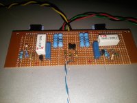
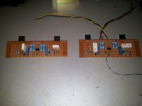
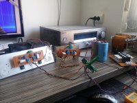
home made f5 🙂
Sounds fantastic on test psu 2x20V, mosfets from ebay. Worked like a charm from the first powerup, no nasty surprises. With 2x100r resistors gain is too low for my sound card, so I guess I'm going to experiment with some higher values there.
Sounds fantastic on test psu 2x20V, mosfets from ebay. Worked like a charm from the first powerup, no nasty surprises. With 2x100r resistors gain is too low for my sound card, so I guess I'm going to experiment with some higher values there.
Attachments
f5 home made
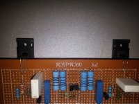
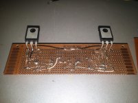
Looks very nice, hardwired f5, only thing ,you properly need a bigger heat sink.
vel done
🙂
Looks very nice, hardwired f5, only thing ,you properly need a bigger heat sink.
vel done
🙂
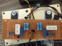
For R21 and R22 is there a consensus as to whether 10K or 22K1 resistors work better? I just soldered the 10K resistors in, and then found the extra set of 22K1 resistors from the kit unused. So, am kicking myself a bit for not knowing this before soldering, but is it really worth replacing the 10K resistors? I have only started one channel, so I am also thinking about building the second channel with the 22K1 to see if there really is a difference (to me). Thoughts? Thanks, Andy
Hi Andy,
I'm not sure, but are you referring to the Vfet2 amp? I'm wondering it you might
have posted this in the wrong thread.
Cheers,
Dennis
I'm not sure, but are you referring to the Vfet2 amp? I'm wondering it you might
have posted this in the wrong thread.
Cheers,
Dennis
22k is preferred. It was a very early schematics where the value was 10k. You're not in trouble though, you're just letting your current limitor kick in a little earlier. If you change it to 22k , the limitor will have less of an impact on the sound.
Dennis, this is the F5. Pico, I'm using the Peter Daniels boards. I might be sqeamish, but the boards are so small that I'm not really looking forward to de-soldering. I might just splice in a 12K like 6L6 did for his bias resistors, though. Thanks, guys! Andy
Which PCB?
just transistors and passive components. the design is NP's IP
- Home
- Amplifiers
- Pass Labs
- F5 power amplifier