Maybe. Your question can be better answered after some more hours with it with a variety of different familiar tunes.
This problem isn't specific to the F5 (I am currently trying to get the grips on the latest version of the Honey Badger using the outdated build guide). The build guides of other designs also don't get enough updates from the community because the documents are not accessible editing; and documentation in the format of discussion threads is rather confusing. A WIKI would be better for community supported documentation or build guides IMHO.Just a thought:
The F5 design lends itself greatly as a beginners build. That's why I guess a lot of simple mistakes end up in this thread.
I suggest people in know update the build instructions? If it's that obvious that these mistakes keep being made.
The age old engineering mistaken assumption: Inside out, versus outside in thinking..
Then I tried a song via spotify premium, thus at 320kbps (I know, still shitty quality, but yes...). I don't know what to say, but the voice really sounded dull, not clear at all. Furthermore I recognized suddenly a lot of echo in the song
You are describing the sound of lossy compression. You are able to hear it now.
In addition to what ZM said, I would simply not put the two output devices back in. You can test the amplifier without the output devices, and check that turning the pots affects the gate voltage. Once you are satisfied, you can solder in the output devices, back down the trimmers to zero and start the biasing from scratch.
How would I connect the voltmeter to check the gate voltage? Negative to circuit ground or elsewhere?
Connecting the voltmeters to the gate (R11 and 14) and circuit ground shows the PS voltage with the pots fully closed. Opening the pots decreases the voltage. Assuming this is OK I'll solder in the Mosfets and rebias.
Well I powered it up with new MOSFETS and new R11, 12, 13 and no smoke, but no bias voltage either. So I assume the other transistors got hit. I just need to find some Jfets and haven't had luck yet.
Hi McQuaide,
What voltages are you getting across the R5/P1 and R6/P2 combinations? When
you said no bias voltage, are you talking about no voltage across R7 and R8?
I'm referring to the schematics show in this post:
http://www.diyaudio.com/forums/pass-labs/121228-f5-power-amplifier-1532.html
In your earlier post I think you're saying that the voltage do change when
you adjust the pots so it seems there's current through the jfets.
Cheers,
Dennis
Hi McQuaide,
What voltages are you getting across the R5/P1 and R6/P2 combinations? When
you said no bias voltage, are you talking about no voltage across R7 and R8?
I'm referring to the schematics show in this post:
http://www.diyaudio.com/forums/pass-labs/121228-f5-power-amplifier-1532.html
In your earlier post I think you're saying that the voltage do change when
you adjust the pots so it seems there's current through the jfets.
Cheers,
Dennis
I'm seeing zero volts across R7 and R8 when I turn the pots. I'll have to pull the amp out and check R5/R6. I didn't realize the schematic in the post has different numbering compared to the PDFs I have so it's a bit confusing.
Any other voltages I should check while I'm in there?
The schematic was very confusing.
Your 2SJ74 is blown, the 2SK170 is likely OK. This is why you don't get the expected 600mV across R2.
The gate voltage is the Gate-Source relative voltage, not the voltage from gate to ground.
This is measured between the Source terminal and gate terminal. In this amplifier, it can also be measured across R3 and R4.
If you have 600mV across R1 and R2, the front end is operating properly. If you get no voltage across R3 and R4 when you turn the pots, the protection is either engaged, or the transistors are connected backwards or have malfunctioned.
If you have proper voltage increase across R3 and R4 when turning pots, but you get abnormal offset values or unpredictable bias (too high/too low/not moving/always at full bias) then the output devices are toast. Depending on what happened to the amp, the source resistors on the output devices might be dead too.
That apart, there's not too much else to go wrong with it. I have had burnt-out feedback resistors once, when the amp blew an output MOSFET and the output was driven to a rail. This caused enough dissipation in the feedback resistor to destroy it as well. However that sort off stuff is quite visible.
Yeah, unfortunately having no voltage across R2 is bad news for the 2sj74. 🙁
Do you know the Idss of the pair you were using? It may be easier obtaining
a new pair than to try getting a single to match the one they may still be working
(assuming it is).
Do you know the Idss of the pair you were using? It may be easier obtaining
a new pair than to try getting a single to match the one they may still be working
(assuming it is).
I have a set of SK and SJ with proper values on the way. I don't know whether the ZTX Q5/Q6 have issues.Thanks all for your help.
Too bad you had to replace these hard to find parts. At least you're well on your way.
If you have any doubt about the ZTX450/550, I would consider just replacing them.
Did you ever determine if the new tube preamp contributed to the failure?
Cheers,
Dennis
If you have any doubt about the ZTX450/550, I would consider just replacing them.
Did you ever determine if the new tube preamp contributed to the failure?
Cheers,
Dennis
If I have to remove the ZTX to test them I'd rather just replace them.
On to the subject of the cause of the failure - here's the schematic of the preamp. The preamp hadn't been powered on for more than a few seconds when I powered up the F5. The oscillation started immediately and the gate resistor smoked in a few seconds.
Anything here that would be of concern? It's a sweet sounding pre that mates well with the F5 but I probably not going to chance it again.
An externally hosted image should be here but it was not working when we last tested it.
Attachments
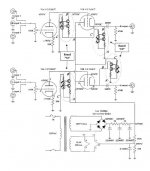
even if schematic is pretty much unreadable , it isn't crucial to analyze it - pretty often physical execution is of same importance as schematic itself
however - important tip - when you see tube schematic with nothing else than pot connected to grid (no grid resistor to gnd!!) , just skip it and leave it for suckers
however - important tip - when you see tube schematic with nothing else than pot connected to grid (no grid resistor to gnd!!) , just skip it and leave it for suckers
I'm not positive about the 'mates well with the F5' comment, seeing as how it turned out.
I also don't much trust tube circuits that directly couple the two tubes. It looks like a pretty standard two-stage pre from the 40s with CCS loads on each tube. Nothing particularly special, or safe.
At the very minimum consider using back to back zeners to clamp the signal across the input of the F5, about 9V - this should protect your investment. Also the caps across drain and gate, to help with local oscillation in the output stage even if you don't have any yet. You don't know what will cause it to kick in.
I don't know what rating of output cap you used on the pre, but I would rate to at least 1.5x the supply voltage. Some builders/kit suppliers would put a 50-100V cap there. At the very least try it with another amp and ensure it is safe before hooking it up to the F5. All of these tube preamps give me the heebie-jeebies.
QFT.
I also don't much trust tube circuits that directly couple the two tubes. It looks like a pretty standard two-stage pre from the 40s with CCS loads on each tube. Nothing particularly special, or safe.
At the very minimum consider using back to back zeners to clamp the signal across the input of the F5, about 9V - this should protect your investment. Also the caps across drain and gate, to help with local oscillation in the output stage even if you don't have any yet. You don't know what will cause it to kick in.
I don't know what rating of output cap you used on the pre, but I would rate to at least 1.5x the supply voltage. Some builders/kit suppliers would put a 50-100V cap there. At the very least try it with another amp and ensure it is safe before hooking it up to the F5. All of these tube preamps give me the heebie-jeebies.
with nothing else than pot connected to grid (no grid resistor to gnd!!) , just skip it and leave it for suckers
QFT.
I'm not positive about the 'mates well with the F5' comment, seeing as how it turned out.
I also don't much trust tube circuits that directly couple the two tubes. It looks like a pretty standard two-stage pre from the 40s with CCS loads on each tube. Nothing particularly special, or safe.
At the very minimum consider using back to back zeners to clamp the signal across the input of the F5, about 9V - this should protect your investment. Also the caps across drain and gate, to help with local oscillation in the output stage even if you don't have any yet. You don't know what will cause it to kick in.
I don't know what rating of output cap you used on the pre, but I would rate to at least 1.5x the supply voltage. Some builders/kit suppliers would put a 50-100V cap there. At the very least try it with another amp and ensure it is safe before hooking it up to the F5. All of these tube preamps give me the heebie-jeebies.
QFT.
"Mates well" meaning SQ and an adequate amount of gain for the F5. But I won't be using the tube pre anymore. I have a nice new Marantz AVR with a respectable preamp stage and I'll go back to that.
- Home
- Amplifiers
- Pass Labs
- F5 power amplifier