+-40mF should be OK.
It will certainly work.
When you first start testing you can measure the hum on the amp output. From that result you can decide whether to add capacitance or add a RC or LC to improve attenuation. There are lot's of solutions. All work.
It will certainly work.
When you first start testing you can measure the hum on the amp output. From that result you can decide whether to add capacitance or add a RC or LC to improve attenuation. There are lot's of solutions. All work.
How does the F5 do for rejecting RF?
I live too close to two radio stations... My Gainclone picks up herendous RF despite everything I do to improve grounding, and adding capacitors to block it (pin 7 and 8 or something).
I am considering building an F5 to go with my Horn Shoppe speakers, but RF is what I truly want to get rid of... sound is fine, but I can barely listen to anything because the RF is so loud.
Have you tried a ferrite bead or two on the input wires? That has always stopped the problem for me, but I have only had issues with my phono stages...
I can try that, but have not yet. I suspect it would, but elimination is very different.
Does it not have an effect on sound with on RCA cords coming in?
Does it not have an effect on sound with on RCA cords coming in?
Last edited:
You are not going to easily get rid of all the RF in the air... 😀 You can remove lots of it from the inputs, therefore solving your problem. 🙂
If you haven't tried something as simple as clip-on ferrite RF suppressors for your interconnects, I would strongly recommend it.
If you haven't tried something as simple as clip-on ferrite RF suppressors for your interconnects, I would strongly recommend it.
Last edited:
The use of tiny litle pin and hammer is a very drastic solution that in no way whatsoever I would suggest especialy if the pin is small enoug so not to be seen and the hammer big enogh to awoid the 13KV like fire work that the litle pin would cause if by chance it causes a shorth on the coaxial cable.
The use of a litle pin is so that they may have to repair the transmitter a few times before they decide to change the coaxial cable and a realy nasty thing that it should never ever ever be done so do not under any circumstancies do that
The law is in your side against air polution...
The use of a litle pin is so that they may have to repair the transmitter a few times before they decide to change the coaxial cable and a realy nasty thing that it should never ever ever be done so do not under any circumstancies do that
The law is in your side against air polution...
Just a way to remove RF from the air that I most strongly deny to have ever done or inteded to do and that I also reccomend that it should never be atempted
Especialy when you are near 2 radio station that may blame each other for such a deed
Especialy when you are near 2 radio station that may blame each other for such a deed
^^ ?? Did I miss something... ???
Bksabath is referring to driving a pin (with a hammer) into the coax of the transmitter, between the transmitter and antenna--in an effort to short out the coax and trip the output monitors on the transmitter (thereby shutting down the station). Certainly, an effective way to reduce RF interference, until the broadcast station radio engineer discovers the source of their problem--and until the local police come knocking on your door.
As a guy who once was a part-time station engineer, this is NOT a practice I would appreciate..... Gggrrrrrr....... 🙄
DJNUBZ,
With CAM's points in mind above, It isn't the actual size of the caps that you're looking for but the QUALITY of those power supply caps - for example, 10,000uF Epcos Sikorel or Nichicon FW (or maybe "Super Thru,s") is going to sound "much better" than the Nuova caps, but much more expensive
(2 x 10,000uF / rail in a C-R-C system is pretty good, IMO = 40,000/ channel) - I found that a second 10,000uF on the second cap (10mF - 0.1R - 2 x 10mF) of Nichicon FW had more bass definition and any more in // didn't do anything, but maybe with 4R speakers or running amp towards max power ...
With the 28V rails and your 400VA trannie, could neatly fit a basic Cmultiplier after the power caps (see First watt F3) to enhance supply and still give you approx 24V rails ...
But, I would suggest just replacing the block bridges if you're using them, assemble the supply with the Nuovos and try it in your system and upgrade later if not satisfied - suggest you don't "skimp" on internal wiring - spend some $s here - and amp has very little "hum" if assembled properly, very quiet indeed.
As has been mentioned often before, with this amp almost any component choice alters it's "sound signature" to some extent so there's quite a bit of flexibility to suit different speakers, etc.
Quote>As a guy who once was a part-time station engineer, this is NOT a practice I would appreciate.....
Exactley my point.Not a nice thing to do
Also mentioned the Law is in your side against air polution
Just write complaint to broadcasting autority is the station that must prove that they comply.
And yes very litle hum on F5 even with 15 foot of cable and ground conected only on Pre amp side in my case
Do you have a ground loop that work as aerial?
Last edited:
Splitting the two rails supply by creating a virtual ground such as Quad used to do works also.
Can you point me to schematics? Or how could be this done?
Is there really no way how to convert F5 for single rail supply?
Why? And wouldn't then be an F5.
- suggest you look up some of the "Prophet" Variations on "L'Audiophile"
- suggest you look up some of the "Prophet" Variations on "L'Audiophile"
Can you point me to schematics? Or how could be this done?
Is there really no way how to convert F5 for single rail supply?
Quad Download Page - quad-606-power-amplifier-schematic.pdf
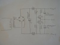
Applied to F5
0V point is floating or connected to the ground? And what are those transistors for? Are they necessary?
Why? And wouldn't then be an F5.

kacernator, than you have to build an F3 amp... 😉
 & for fun
0V point is floating or connected to the ground? And what are those transistors for? Are they necessary?
0v is the reference point connected to ground.
The transistors avoid a drift due to unperfect symetry.
They are necessary.
I used BD139/140 without heatsinks.
kacernator, than you have to build an F3 amp... 😉
Definitely not. F3 is single ended, has worse distortion and higher output impedance than F5.
But thanks anyway.
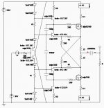
New circuit
And what about this circuit? It is circuit based on the schematics from earlier post (moskido schematics), but it should have no temperature drift already. Do you know how to adjust bias on this scheme? If I wanted to implement temperature thermistor, where should I connect it?
Thanks.
And what about this circuit? It is circuit based on the schematics from earlier post (moskido schematics), but it should have no temperature drift already. Do you know how to adjust bias on this scheme? If I wanted to implement temperature thermistor, where should I connect it?
Thanks.
Attachments
Last edited:
- Home
- Amplifiers
- Pass Labs
- F5 power amplifier