I finally found the issue and bought it yesterday. I think the best plan is to put the PS in an outboard enclosure to run whichever Fx amplifier you have. It is an extra enclosure, two extra connectors, and PS cable, but I think it is worth it.
The Hybrid SE OTL artice was also very cool.
Thank you Nelson!
Chris
The Hybrid SE OTL artice was also very cool.
Thank you Nelson!
Chris
some FET models here (unfortunately not exactly the ones needed):
http://www.diyaudio.com/forums/showthread.php?postid=1420730#post1420730
You can step through any Idss/Vto per sim at will, if you locally include the models and make the relevant model values parametric. Or make hard coded model variations, name the models purely numerically and loop through them (with LTSpice that works, at least).
Also, you can adjust the feedback divider impedance level (which sets JFET-bias), even independantly for each branch.
- Klaus
chrismercurio said:I finally found the issue and bought it yesterday. I think the best plan is to put the PS in an outboard enclosure to run whichever Fx amplifier you have. It is an extra enclosure, two extra connectors, and PS cable, but I think it is worth it.
The Hybrid SE OTL artice was also very cool.
Thank you Nelson!
Chris
Good idea!!That is what I've done and am pleased to have done it. Nelson Pass has done us great service with his designs in so many ways. One 18-0-18 volt unit goes a looong way!!
As for models?... The only model one needs is the schematic...Why second guess a Genius?? The finished product is commercially available!!!
KSTR said:some FET models here (unfortunately not exactly the ones needed):
http://www.diyaudio.com/forums/showthread.php?postid=1420730#post1420730
You can step through any Idss/Vto per sim at will, if you locally include the models and make the relevant model values parametric. Or make hard coded model variations, name the models purely numerically and loop through them (with LTSpice that works, at least).
Also, you can adjust the feedback divider impedance level (which sets JFET-bias), even independantly for each branch.
- Klaus
thank you very much.
I'll try to set the Idss to 6mA and see what's new.
just don't get the reason of why i should set the Idss on the model
Is it nor determined by the specific part and and the circuitry around?!
..oh well...
Stefanoo said:
just don't get the reason of why i should set the Idss on the model
Is it nor determined by the specific part and and the circuitry around?!
..oh well...
There is often a wide spread in Idss values. For example,
the Idss for 2sk170BL is specified as between 6 to 12mA.
The other day I measured the Idss of 100 such parts and
the values were pretty much scattered within that range.
I was finishing up my F4 (as I have been doing for months, 🙄 ) and decided to keep the power supply separate also. Clearly there is a trend with the First Watt amps to have very similar power supplies. Makes sense as it spares Nelson the complexity and expense of designing and building a different power supply for each model- especially the hassle of ordering new parts..
Neutrik makes some nifty three pole (positive rail, ground, negative rail) twist-lock connectors that are ideal for this. (Mouser has 'em.) I've been doing it for years. Why let the preamp guys have all the fun?
Grey
Grey
I am so fascinated with the non-C design of F5. I made mine and it just sounds great to me.
While many of you go for higher power, I am thinking about mod F5 for my AKG K240 DF earphone, 600 ohm.
Any suggestion please?
One more question,
I assume it is no harm if I remove R15/TH1 and R16/TH2, right?
While many of you go for higher power, I am thinking about mod F5 for my AKG K240 DF earphone, 600 ohm.
Any suggestion please?
One more question,
I assume it is no harm if I remove R15/TH1 and R16/TH2, right?
My personal experience with this has been via Jeff Rowland, Aesthetix, Sonic Frontiers gear...and of course Pass Labs. I can remember Cardas and Neutrik in a few cases....but I think Jim White at Aesthetix was using something else.
Chris
Chris
genome said:I assume it is no harm if I remove R15/TH1 and R16/TH2, right?
As long as you don't mind more time spent warming up and adjusting.
external PS
Is there a problem just running standard XLR's here, with some 18GA cable? Will too much current melt the connectors plastic?
My battery powered tube preamp is using them with Cat5 cable without any issue. ( I know of)
Mike
GRollins said:Neutrik makes some nifty three pole (positive rail, ground, negative rail) twist-lock connectors that are ideal for this. (Mouser has 'em.) I've been doing it for years. Why let the preamp guys have all the fun?
Grey
Is there a problem just running standard XLR's here, with some 18GA cable? Will too much current melt the connectors plastic?
My battery powered tube preamp is using them with Cat5 cable without any issue. ( I know of)
Mike
Speakon's have up to 8 contacts, and are made for higher amperage-30A continuous according to the spec sheet. . Also are non-shorting...
They are my plan- unless I have a row of speaker type terminals....
and spade connectors on the wires.
http://www.partsexpress.com/pe/showdetl.cfm?&Partnumber=092-050
http://www.partsexpress.com/pe/showdetl.cfm?&Partnumber=092-051
http://www.partsexpress.com/pe/showdetl.cfm?&Partnumber=092-052
http://www.partsexpress.com/pe/showdetl.cfm?&Partnumber=092-053
http://www.partsexpress.com/pe/showdetl.cfm?Partnumber=092-054
http://www.partsexpress.com/tech/092-051.html
etc
Re: external PS
I think he's talking about the "PowerCon" version which is normally for 20a AC 3-wire line, sort of as a replacement for IEC connector, but locking. I try not to use 3-pin XLR's for power since they're too easily confused. Maybe the 4-pin version, but still great for much current.mithomas said:
Is there a problem just running standard XLR's here, with some 18GA cable? Will too much current melt the connectors plastic?
My battery powered tube preamp is using them with Cat5 cable without any issue. ( I know of)
Mike
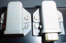
For that kind of connections i've been using Hirschmann Stas/Stak for decades, assembled a 3-piece Gerard Perrot (Mr Lavardin) amplifier design that was published in l'audiophile with them.
The Stas/Stak connector system is also highly water resistant, from 2 to 5 pole versions, example
A picture of the 2-pin types =>
The Stas/Stak connector system is also highly water resistant, from 2 to 5 pole versions, example
A picture of the 2-pin types =>
Attachments
KSTR said:"The feedback mechanism for this amplifier is R3 through R6, a dual pair of low impedance voltage dividers which feed the output to the Source pins of Q1 and Q2. Low impedance feedback has been (incorrectly) referred to as 'current feedback'"
I read a book:
Whenever the feedback voltage is proportional to output current, the circuit has current feedback. Current feed back stabilizes the output current. This means that a constant input voltage produces an almost constant output current, despite changes in open-loop gain and load resistance. For instance, suppose the open-loop voltage gain decreases. Then the output current tries to decrease. This results in less feedback voltage and more error voltage. In turn, this means more output voltage and current. The increased error voltage almost completely offsets the decrease in open-loop voltage gain, so that the output current remains almost constant. A similar argument applies to an increase in open-loop gain. Attempted increases in output current are almost eliminated by the negative feedback.
Noninverting Current Feedback:
Transconductance -- Decreases
Input impedance -- Increases
Output impedance -- Increases
Distortion -- Decreases
Output offset -- Decreases
Inverting Current Feedback:
Current gain -- Stabilizes
Input impedance -- Decreases
Output impedance -- Increases
Distortion -- Decreases
Output offset -- Decreases
For this, the load resitor (speaker) and feedback resistor are in series, as I understand...
Hope I did no mistyping...
Babowana said:
I read a book:
Whenever the feedback voltage is proportional to output current, the circuit has current feedback. Current feed back stabilizes the output current. This means that a constant input voltage produces an almost constant output current, despite changes in open-loop gain and load resistance. For instance, suppose the open-loop voltage gain decreases. Then the output current tries to decrease. This results in less feedback voltage and more error voltage. In turn, this means more output voltage and current. The increased error voltage almost completely offsets the decrease in open-loop voltage gain, so that the output current remains almost constant. A similar argument applies to an increase in open-loop gain. Attempted increases in output current are almost eliminated by the negative feedback.
Noninverting Current Feedback:
Transconductance -- Decreases
Input impedance -- Increases
Output impedance -- Increases
Distortion -- Decreases
Output offset -- Decreases
Inverting Current Feedback:
Current gain -- Stabilizes
Input impedance -- Decreases
Output impedance -- Increases
Distortion -- Decreases
Output offset -- Decreases
For this, the load resitor (speaker) and feedback resistor are in series, as I understand...
Hope I did no mistyping...
I too did some research and found similiar info. The problem is it applied to a standard op-amp config which this amp is not. Oddly this feedback principle is not really covered in the article while it probably has a great deal to do with proformance. Anybody draw a diagram showing what goes on??
I think you have the wrong idea here. The F5 uses what I would
refer to as low impedance voltage feedback - as pointed out earlier
the circuit is a CFP "complementary feedback pair" variant.
Maybe it should be called a complementary-complementary-feedback-
pair-with-voltage-gain. CCFPWVG is a snappy acronym, no?
The point of my comment in the article is that this is routinely
referred to as "current feedback" in the op amp literature, but it has
been mis-named in this regard.
Re: Re: external PS
So in theory XLR's or "microphone" jacks can be okay (I use one per channel).
I have not tried it with 1stWatt amps yet, but plan on doing so as well. I have plenty of XLR's right now, no power or speakerconns.
tms0425 said:I think he's talking about the "PowerCon" version which is normally for 20a AC 3-wire line, sort of as a replacement for IEC connector, but locking. I try not to use 3-pin XLR's for power since they're too easily confused. Maybe the 4-pin version, but still great for much current.
So in theory XLR's or "microphone" jacks can be okay (I use one per channel).
I have not tried it with 1stWatt amps yet, but plan on doing so as well. I have plenty of XLR's right now, no power or speakerconns.
- Home
- Amplifiers
- Pass Labs
- F5 power amplifier