Conrad
These guys are in Au. Way down under... Looks like great work.
Hows about some US supply house
and may a part number?
These guys are in Au. Way down under... Looks like great work.
Hows about some US supply house
and may a part number?
How about M&M in Texas? This profile might be useful:
http://www.mmmetals.com/extrusions/drawings/MK62430.jpg
http://www.mmmetals.com/extrusions/drawings/MK62430.jpg
Phil,
There was a group buy for the Conrad sinks. They may be extras if you check here http://www.diyaudio.com/forums/showthread.php?s=&threadid=117303&perpage=25&pagenumber=13
There was a group buy for the Conrad sinks. They may be extras if you check here http://www.diyaudio.com/forums/showthread.php?s=&threadid=117303&perpage=25&pagenumber=13
M&M Metals
I have been in touch with M&M metals regarding this profile.
http://www.mmmetals.com/extrusions/drawings/MK62430.jpg
I have a few quotes for 7" high sections and I am hoping to arrange either a group buy or even a group discount if they are willing to work with us. Also, ebayer Barredboss found Here ( http://myworld.ebay.com/barrredboss/?_trksid=p3911.c0.m198 ) is looking into designing a 12" extrusion. I am encouraging him to come to our forum and work with us directly through the vendors section.
Nick
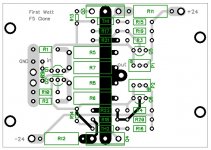
Hello everyone,
I finished my own F5 pcb layout based on Peters F4 pcb size and fet location. Since this is the first time I designed a board and have them professionally made I was hoping someone is willing to do a review of my design (specially the gerber files) before I have them made. It would be a shame if I ended up with a bunch of worthless boards. I've added the gerber files and diptrace file to the attached .zip file.
Help will be really appreciated!!
cheers,
c.
Attachments
pcb mods
Hi Cukture,
If you were to move the Q3, R11, etc to the left a bit (also Q4, R12, etc to the right) there would be ample room to add a Cmultiplier like PD did on his F3 pcb.
Nice design.
Hi Cukture,
If you were to move the Q3, R11, etc to the left a bit (also Q4, R12, etc to the right) there would be ample room to add a Cmultiplier like PD did on his F3 pcb.
Nice design.
cviller said:I'm currently using the 40cm 3u version for my f5 and it does not get too hot at all. In fact I think the 30cm would be sufficient.
I think i will purchase the 30cm version, as it is quite a bit cheaper then the 40cm. I could allways place a fan on the back panel.
Also, i see this amplifier requires 24v rails. Do you think i would get away with 25v capacitors, as they are half the cost of 63v, and a lot smaller in size...
NO!rhysh said:Also, i see this amplifier requires 24v rails. Do you think i would get away with 25v capacitors, as they are half the cost of 63v, and a lot smaller in size...
what voltage appears on the output of the rectifiers if the mains voltage varies?
Here in the UK the tolerance is 216Vac to 254Vac. If you use a 230:18Vac transformer on the standard UK voltage it will measure ~18.8Vac when fully loaded.
On 254Vac it will measure ~19.9Vac when fully loaded. when unloaded these voltages will increase by the transformer regulation percentage. Big toroids can be as low as 3%, small EI can be as high as 30%. Find out the regulation of your transformer and adjust the output voltage assuming the PSU output fuses have blown and the caps are now charging up to the peak AC voltage going through the rectifiers.
Mains voltage variations can be surprisingly large and can overvoltage components if ignored. Measure and check, or easier, allow a margin on ratings for the variations that will occur.
BTW, electrolytics are available at many voltages between 25Vdc and 63Vdc, common available are 35V, 50V and less common 40V.
Finally, expect your PSU cost to be more than the cost of the amplifier and heatsinks.
rhysh said:...Do you think i would get away with 25v capacitors...
You might, but only if you use well regulated power supply - but OTOH the voltage reg will cost you more than price difference between 25V and 35V or 40V caps. That's one of those "expensive savings" ...

Also, using components in "close to limit" area compromises reliability of the amp and makes the whole thing dangerous, so please think again 😉
and what if the voltage regulator fails or has a tolerance on output voltage?
What about the smoothing before the regulator?
What about the smoothing before the regulator?
AndrewT said:
NO!
what voltage appears on the output of the rectifiers if the mains voltage varies?
Here in the UK the tolerance is 216Vac to 254Vac. If you use a 230:18Vac transformer on the standard UK voltage it will measure ~18.8Vac when fully loaded.
On 254Vac it will measure ~19.9Vac when fully loaded. when unloaded these voltages will increase by the transformer regulation percentage. Big toroids can be as low as 3%, small EI can be as high as 30%. Find out the regulation of your transformer and adjust the output voltage assuming the PSU output fuses have blown and the caps are now charging up to the peak AC voltage going through the rectifiers.
Mains voltage variations can be surprisingly large and can overvoltage components if ignored. Measure and check, or easier, allow a margin on ratings for the variations that will occur.
BTW, electrolytics are available at many voltages between 25Vdc and 63Vdc, common available are 35V, 50V and less common 40V.
Finally, expect your PSU cost to be more than the cost of the amplifier and heatsinks.
Thankyou for the info, i have realised i can get the same part in 35V for not much more. I have decided on 2 x 100,000uf Rifa capacitors per rail, do you think this should be okay?
AndrewT said:and what if the voltage regulator fails or has a tolerance on output voltage?
What about the smoothing before the regulator?
Right ! That's exactly why even that solution won't be very feasible in this case ...
rhysh said:
Thankyou for the info, i have realised i can get the same part in 35V for not much more. I have decided on 2 x 100,000uf Rifa capacitors per rail, do you think this should be okay?
Sounds very good. 😉
Hi all.
I am a bit confused regarding the best voltage for rails, I seem to remember Mr Pass saying 25v rails are minimum and any lower every volt makes a difference, but then everybody uses 18v secondaries which after rectifiers, voltage drop etc gives approx 23.5v rails. Why not use 20v secondaries or even 22v ?
What have I missed ?
Thanks.
jotom750 said:Hi all.
I am a bit confused regarding the best voltage for rails, I seem to remember Mr Pass saying 25v rails are minimum and any lower every volt makes a difference, but then everybody uses 18v secondaries which after rectifiers, voltage drop etc gives approx 23.5v rails. Why not use 20v secondaries or even 22v ?
What have I missed ?
Thanks.
I don't think he said minimum of 25V. The amplifier works best with 24 volt rails. Try to get as close to 24V as possble. If the voltage is too high it will probably have to dissipate more heat, and may not sound the same.
low sound
hi..today i built f5 amp with huge heatsinks..i used 2sk1530 and sj201. bias is 1,5a and i see 2,83volts on r3 and r4..but the sound is very low.my soundcard is emu1212m and has enough output.what is the problem? i couldnt solve it
hi..today i built f5 amp with huge heatsinks..i used 2sk1530 and sj201. bias is 1,5a and i see 2,83volts on r3 and r4..but the sound is very low.my soundcard is emu1212m and has enough output.what is the problem? i couldnt solve it
Re: low sound
I would check it with a function generator and a scope before hooking it to a source and speakers.
umut1001 said:hi..today i built f5 amp with huge heatsinks..i used 2sk1530 and sj201. bias is 1,5a and i see 2,83volts on r3 and r4..but the sound is very low.my soundcard is emu1212m and has enough output.what is the problem? i couldnt solve it
I would check it with a function generator and a scope before hooking it to a source and speakers.
- Home
- Amplifiers
- Pass Labs
- F5 power amplifier