Hi All,
After years of working flowless my F5 plays on both channels but on one side the transistors are staying cold (not ever warm)
I'm getting .59 volts across R12
Any ideas what this could be?
Thank you all,
IK
After years of working flowless my F5 plays on both channels but on one side the transistors are staying cold (not ever warm)
I'm getting .59 volts across R12
Any ideas what this could be?
Thank you all,
IK
I'm getting .59 volts across R12
How about R11? And what is the output DC offset voltage?
Thanks so much for trying to help
When amp is cold I get
R12-0
R11-0.52
R1-0.08
R2-0.1
R3-0.11
Offset-0.73
When amp is cold I get
R12-0
R11-0.52
R1-0.08
R2-0.1
R3-0.11
Offset-0.73
In your original post you said you were getting 0V59 across R12.
In post #5 you said 0V0 across R12.
Can you clarify? Did it change or was one noted in error?
In post #5 you said 0V0 across R12.
Can you clarify? Did it change or was one noted in error?
There's some issue with the R3/R4 R11/R12 numbers. If R3 is 0, R11 will also be zero. If you're getting R4 3.86 then R12 should be around .6. Yours seem opposite. Can you pl recheck?
JFETs seem to be okay, so it's either current limiting cutting in (my primary suspect) or an output device.
JFETs seem to be okay, so it's either current limiting cutting in (my primary suspect) or an output device.
With the power off, what is the resistance across P1? If the pot has failed it will show zero and turning the screw will make no difference.
If it is greater than zero (around 450 ohms should be the present reading), turn both P1 and P2 to zero.
Remove Q5.
Put the bulb limiter on your mains input OR power the amp through 10 ohm resistors.
Start moving P1/P2 till you start getting some bias, to verify whether everything is functioning per normal. About 50mV across R11 and R12 will verify that you're doing okay.
Replace Q5 with a known good part. Note the pin orientation carefully. Reversed device will lead to zero bias.
Definitely follow Sangram's advice. I am only offering a suggestion that you can check to see if P1 has failed by checking the resistance across R5. It may save you from having to remove the board from the heatsinks. If you can confidently replace Q5 w/o removing the board from the heatsinks, it could save you some time and another potential failure mode during troubleshooting/repair.
Sangram or another person with more experience can chime in if that is recommended/proper.
Sangram or another person with more experience can chime in if that is recommended/proper.
Actually the resistance across P1 is measurable between collector and emitter of Q5. Those leads are fully exposed and available, probably easier than a resistor too. There are other possibilities, one of which is the power supply rail, one end of the thermistor, etc.
As long as you get a reading, it doesn't matter where you take it.
As long as you get a reading, it doesn't matter where you take it.
Definitely! Also, thank you. I chose R5 b/c it is commonly used as a reference when people forget to zero P1 (or are anxious about it) before their first biasing, but after installing the pots on the boards and/or mounting the boards. I should have offered alternatives to be more complete. Of course, I did not mean to assume anything re: IZHAKKATZ's ability to determine that on their own.
Does the reading change as you turn the trimmer? Either direction is fine, it needs to go up and down.
If it doesn't, take Q5 out and measure again.
If it doesn't, take Q5 out and measure again.
My bet is Q4 is blown, or something in its drain/source is open on the way to the output. I get about .072 volts offset under such a condition by hand calculations. Did you miss a zero for your offset measurement?
Please re-measure, and make sure you are referencing the correct resistors. As it stands, things don't seem to add up. If things actually are as previously quoted, you have a real mess on your hands.
- Home
- Amplifiers
- Pass Labs
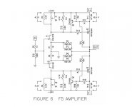
- F5 Help