In the 2107 case it would look something like this, depending on your choice of regulator. Mine is 317/337 followed by a cap reg under the input jack. Transformer is 50va Antek. Would be very tight if dual mono in this case unless you go to a one board solution like EVULs pcb.
Another option would be to mount the amp boards on the bottom and regs on the heat sinks.
Another option would be to mount the amp boards on the bottom and regs on the heat sinks.
Attachments

2107 is big enough for dual mono, even with P2P.
Just need to plan well and build compact.
2109 is what Stixx used for the DAO SE, with lots more boards.
Patrick
Just need to plan well and build compact.
2109 is what Stixx used for the DAO SE, with lots more boards.
Patrick
Hikari: With small 25VA r-cores it would be possible i think, they are approx ~70x80mm size. And there is always small toroidals which probably is even more compact.
I was thinking if i shall try with the Salas boards i already have, or if i shall make new regulator boards with LDO + cap multi... My Salas boards may be hard mounting in the 2107 on the sides, while i know the fit on the 2109 side sinks.
I was thinking if i shall try with the Salas boards i already have, or if i shall make new regulator boards with LDO + cap multi... My Salas boards may be hard mounting in the 2107 on the sides, while i know the fit on the 2109 side sinks.
Iam running a 18v transformer with 15.5v or so rails and 225ma of bias. I haven't calculated the dissapation but the regs may produce more heat than the amp boards. With a shunt reg (keep in mind the concerns with this circuit and some regs earlier in this thread) the shunt will most likely produce more heat then the amp boards depending on the current.
It actually makes a lot sense to do it how evul has done it with his boards. Amp on bottom.
I don't do a lot of headphone amps or small chassis projects, efficiency of space is not something I usually worry about but fitting everything into a small chassis while keeping things logical and well laid out while dealing with close proximity to transformers certainly requires some thinking.
Is it possible to post the most current schematic (with decoupling caps, 1 kOhm gate stoppers and PSU) in post #1 ?
That would help to keep track at all info at one place instead of needing to keep up with searching the thread etc.
Thank you
That would help to keep track at all info at one place instead of needing to keep up with searching the thread etc.
Thank you
Have you read the PDF?
http://xen-audio.com/documents/f5ha/F5-HA Description V1.4.pdf
Everything you need except some of the more exotic PSU options.
http://xen-audio.com/documents/f5ha/F5-HA Description V1.4.pdf
Everything you need except some of the more exotic PSU options.
Actually first time I have seen the PDF. It would have been good to link it from post 1. It appears Inhave built the current feedback variant? I only have 4 active devices. Post 1 veroboard doesn't look like anything in the PDF.
Read carefully. Post 1 is exactly what is in the PDF minus the current limiting. That's what the extra set of ztx devices is for. And the gate resistors have changed from post 1 to 2k. And Fairchild mosfets. That's it.
Running the amp is current sense mode is discussed in the PDF but it has nothing to do with the veroboard layout in post 1.
Running the amp is current sense mode is discussed in the PDF but it has nothing to do with the veroboard layout in post 1.
Read carefully. Post 1 is exactly what is in the PDF minus the current limiting. That's what the extra set of ztx devices is for. And the gate resistors have changed from post 1 to 2k. And Fairchild mosfets. That's it.
I think you missed out the R10a and R10b (I know, they are set to 0 ohm) 😀. If you think the schematic transcribed from the vero board and the schematic shown on p.10 (figure 1) are exactly the same, that's fine with me 😀
Regards,
Speaking of current mode for this amp has anyone tried this as described in the PDF? If so, what were the results. It's pretty interesting in theory.
Would like to ask the opinions of the folks here about the following data. I have located a vendor who claimed to have matched quads of 2SJ74BL and 2SK170 BL (2 each) available (Idss within 2%). The vendor is kind enough to send me a traced curve of a matched quad. Any opinions or comments will be appreciated.
Regards,
Regards,
Attachments
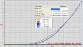
Someone should write a "'Matching FETs for Dummies". I still don't know what exactly is being measured and plotted. Really, there is only one thing that can be measured - voltage. So it's voltage across a source or supply resistor vs gate voltage? the graphs always show some parameter vs another parameter. Take for example, the above curve. It has no units - so what are we looking at??
The curves look very much like the ones in the datasheet, so I incline to think they're real, with Idss of around 7.5mA.
It has no units - so what are we looking at??
That's the Id vs Vgs curve.
Would like to ask the opinions of the folks here about the following data. I have located a vendor who claimed to have matched quads of 2SJ74BL and 2SK170 BL (2 each) available (Idss within 2%). The vendor is kind enough to send me a traced curve of a matched quad. Any opinions or comments will be appreciated.
Regards,
Idvg curves look genuine
Sent from my iPhone using Tapatalk
I think if they are a good price you should buy as many as you will need in the future.
I think 2sk170/sj174 prices are going to get crazy in the near future. If they are not crazy enough already.
I think 2sk170/sj174 prices are going to get crazy in the near future. If they are not crazy enough already.
I think if they are a good price you should buy as many as you will need in the future.
I think 2sk170/sj174 prices are going to get crazy in the near future. If they are not crazy enough already.
Totally agree. It is expensive enough now😱 Just curious, are there no current production JFETs that can be used instead?
Regards,
The curves look very much like the ones in the datasheet, so I incline to think they're real, with Idss of around 7.5mA.
Thank you for the comments. Do you think the quad in this trace are well matched? Look like one of them is off a little.
Regards,
Totally agree. It is expensive enough now😱 Just curious, are there no current production JFETs that can be used instead?
Regards,
You know where I got mine from and they work well. Just sayin'...
Thank you for the comments. Do you think the quad in this trace are well matched? Look like one of them is off a little.
Regards,
They're Idss matched, but as you said they're not fully curve matched.
That said, expect fully curve matched quads is a bit unrealistic nowadays. Even if you manage to find a seller who'll do this, expect to be charged for a further premium.
- Home
- Amplifiers
- Pass Labs
- F5 Headamp ?