I got big heatsinks for it but the bias still climbs. Could it be because the mosfets are damaged? I even upped the gate resistors to 2k ohm to stabilize it.
What is the heatsink temperature after 30 minutes ?
Changing the gate resistors has no effect on bias stability.
You can increase the source resistors to say 6.8R 2W, and readjust the bias.
Patrick
Changing the gate resistors has no effect on bias stability.
You can increase the source resistors to say 6.8R 2W, and readjust the bias.
Patrick
Bias issue has been solved- i cleaned the pcb and swapped out the mosfets and now its stable.
How can i get this circuit to work with irfp9240/240 btw? With the same psu voltage?
I have a stash of them just begging to be used... 🙂
How can i get this circuit to work with irfp9240/240 btw? With the same psu voltage?
I have a stash of them just begging to be used... 🙂
Having read all 111 pages of this thread, I have decided to go on and build this little head amp. Having decided to use the LM3x7/cap multiplier PSU, I have a couple of questions regarding the power supply:
1. In the manual (F5-HA Description V1.4.pdf) there is a Bill of Materials for the LM3x7/cap multiplier PSU, but I couldn't find the schematic that it is referred to.
2. Regarding the rectifier diodes, is there any difference if using Schottky diodes (e.g., MBR745) instead of soft recovery MSR860?
Thanks a lot
Evangelos
1) Read post #137 again.
2) I have never used Schttky's, but there are many threads here comparing the two types.
So you can draw your own conclusion.
Thank you for your interest,
Patrick
2) I have never used Schttky's, but there are many threads here comparing the two types.
So you can draw your own conclusion.
Thank you for your interest,
Patrick
Hi Patrick,
Thank you for your response
That's exactly what I had in mind, but I asked because I noticed some discrepancies. So, let me make some guesses.
1. In the BOM there is no input cap before the regulator (3300 μF in the schematic). So, the numbering of the caps in the BOM refers to the actual regulator/cap multiplier.
2. ADJ bypass capacitor (100 μF in the schematic) is now 47 μF.
3. Output capacitor (C6 - 330 μF in the schematic) is omitted, as there is an on-board bypass capacitor in the amp board.
We are the ones to thank you for providing the community with your knowledge and great ideas.
Regards,
Evangelos
Thank you for your response
1) Read post #137 again.
That's exactly what I had in mind, but I asked because I noticed some discrepancies. So, let me make some guesses.
1. In the BOM there is no input cap before the regulator (3300 μF in the schematic). So, the numbering of the caps in the BOM refers to the actual regulator/cap multiplier.
2. ADJ bypass capacitor (100 μF in the schematic) is now 47 μF.
3. Output capacitor (C6 - 330 μF in the schematic) is omitted, as there is an on-board bypass capacitor in the amp board.
Thank you for your interest,
Patrick
We are the ones to thank you for providing the community with your knowledge and great ideas.
Regards,
Evangelos
The BoM refers to the parts required to populate Ca Multiplier PCBs from us.
Nothing holly.
You are free to try something else as it pleases you.
And you should also perhaps check the F5HA Build thread at the Pass forum for any updates from the Beta testers.
http://www.diyaudio.com/forums/pass-labs/283387-f5-ha-build-thread.html
Patrick
Nothing holly.
You are free to try something else as it pleases you.
And you should also perhaps check the F5HA Build thread at the Pass forum for any updates from the Beta testers.
http://www.diyaudio.com/forums/pass-labs/283387-f5-ha-build-thread.html
Patrick
Kenev,
since you will be building P2P (I assume) you are free to try your own choices (as Patrick said a few minutes ago 😉 ).
Prefilter caps can be anything from 3300uF to 10000uF or more, depending on your layout and available space.
since you will be building P2P (I assume) you are free to try your own choices (as Patrick said a few minutes ago 😉 ).
Prefilter caps can be anything from 3300uF to 10000uF or more, depending on your layout and available space.
sorry i havent yet messed with the sim but i haven been fiddling with my physical build quite a bit. 🙂
i notice that the even order harmonic increases if the positive rail's voltage is higher than the negative rail's. could someone please elaborate why that is, if my observation is right?
and can i add p3 adjuster much like one in F5 and BA-3 to this headphone circuit to tweak the harmonic profile?
here's BA-3 circuit for reference.


Blackdod,
could you possibly post bigger images?
Just kidding, very nice and clean build!
Hope you enjoy it!
could you possibly post bigger images?
Just kidding, very nice and clean build!
Hope you enjoy it!
Happy New Year to all.
Hopefully we shall see more than one example being finished than the only one in 2017.
Too much of a waste just to hang those PCBs on the wall.
😉
Patrick
Hopefully we shall see more than one example being finished than the only one in 2017.
Too much of a waste just to hang those PCBs on the wall.
😉
Patrick
Happy New Year to you, too, Patrick.
LOL, thought I would have more DIY time after reaching retiring status, but the reality has been more traveling instead. That's what the significant half prefers to make up the time spent on raising kids, just can't argue 🙂
LOL, thought I would have more DIY time after reaching retiring status, but the reality has been more traveling instead. That's what the significant half prefers to make up the time spent on raising kids, just can't argue 🙂
Have to have a few days home between trips to get clothes washed, etc. Not ? 🙂
With all parts around, will only take 2~3 days to build, unlike the DAO.
Cheers,
Patrick
With all parts around, will only take 2~3 days to build, unlike the DAO.
Cheers,
Patrick
I can only second Patrick, Fred!
One day you will be tired from travelling, and then you want to sit down in your favourite recliner
and listen to some good music via your headphones and a really good headphone amp...
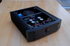
Taking this chance to post a few images of my finished F5HA (finished months ago, only added the decals...). Sounding superb!
Err, that one took longer than 3 days to build. 😀
One day you will be tired from travelling, and then you want to sit down in your favourite recliner
and listen to some good music via your headphones and a really good headphone amp...
Taking this chance to post a few images of my finished F5HA (finished months ago, only added the decals...). Sounding superb!
Err, that one took longer than 3 days to build. 😀
Attachments
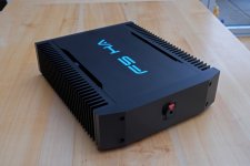
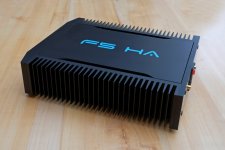
Gorgeous case.
And big enough case and power supply to upgrade to a balanced F5X-HA later.
😉
Patrick
And big enough case and power supply to upgrade to a balanced F5X-HA later.
😉
Patrick
- Home
- Amplifiers
- Pass Labs
- F5 Headamp ?