Are you using cross feed ?
If so I suggest you use a gain of 11 instead of 6.
I post here a DWG file for the bottom plate with all the holes required for mounting MOSFETs and PCB.
There are many free DWG reader software available, e.g. Draft Sight.
Just use any of them and print 1:1 in mm.
The plate outside dimensions are 246mm x 177mm on the drawing.
So you can use that to check your printer setting.
Patrick
Thanks Patrick, a DWG file is perfect 🙂
For the gain, it's currently 6 (per BOM) as I'll first try it without cross feed, get familiar with the sound before swapping in the cross feed and then compare. If cross feed stays at the end, I'll increase the gain.
Dear Patrick and cwtim01,
I see not pots on the cross fed circuit. Are you just building it with the values in the schematic ?
Beside the j-fet of the follower are you adding other components ?
D.
P.S.: I'll start the cross fed as soon as I source the caps, I miss some values for building.
I see not pots on the cross fed circuit. Are you just building it with the values in the schematic ?
Beside the j-fet of the follower are you adding other components ?
D.
P.S.: I'll start the cross fed as soon as I source the caps, I miss some values for building.
If u are referring to the Danyuk crossfeed, the pot are replaced with fixed resistors in my build. I adjusted with the pots to taste and replace them with equivalent values
Correct. The value posted are the values that I like.
But you might like a different amount of cross feed and a different frequency.
So like Cloud85 and as described by Danyuk, use pot to test and then replaced by fixed R's.
The Meier and the Modified Linkwitz all specified fixed values.
But most of us now are using the XEN modified Danyuk.
Don't forget to increase gain when using (any) cross feed.
Patrick
Patrick,
What you refer as the "XEN modified Danyuk" is the circuit on the first page or second of the appendix ? I read the article many time and I understand that the first picture is a "XEN modified Danyuk" the second a"XEN modified CMoy" with treble boost.
D.
What you refer as the "XEN modified Danyuk" is the circuit on the first page or second of the appendix ? I read the article many time and I understand that the first picture is a "XEN modified Danyuk" the second a"XEN modified CMoy" with treble boost.
D.
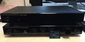
Finished
Further work after the Chinese New Year break, and it's now playing music without Cross Feed 🙂.
I'm not good at describing sound, lets just say it has done enough to displace the amp in the second picture from my primary rig.
Further work after the Chinese New Year break, and it's now playing music without Cross Feed 🙂.
I'm not good at describing sound, lets just say it has done enough to displace the amp in the second picture from my primary rig.
Attachments
Congratulations. And another happy owner. 🙂
Good to know that it beats a 3k USD Gilmore commercial amp and not just a DIY version.
http://www.diyaudio.com/forums/pass-labs/271926-f5-headamp-5.html#post4374209
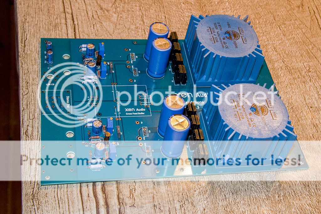
I like those copper plates.
But you might wish to use grease and mica instead, and grease between heat sink and copper.
The grease will prevent the surface from oxidising which will impair conductivity.
And use a good pot, such as a switched ladder attenuator.
Or use wires to connect the pot (instead of solder on the PCB) so that upgrade is easier later without destroying the PCB.
See also :
http://www.diyaudio.com/forums/head...ss-zgf-headphone-amplifier-4.html#post4347276
Patrick
Good to know that it beats a 3k USD Gilmore commercial amp and not just a DIY version.
http://www.diyaudio.com/forums/pass-labs/271926-f5-headamp-5.html#post4374209
I like those copper plates.
But you might wish to use grease and mica instead, and grease between heat sink and copper.
The grease will prevent the surface from oxidising which will impair conductivity.
And use a good pot, such as a switched ladder attenuator.
Or use wires to connect the pot (instead of solder on the PCB) so that upgrade is easier later without destroying the PCB.
See also :
http://www.diyaudio.com/forums/head...ss-zgf-headphone-amplifier-4.html#post4347276
Patrick
Last edited:
Thanks Patrick, it's a lot of work to replace the silpads so I'll probably keep it as it is. (I'll use mica and grease in case I build a second one)
The pot looks ugly but it is actually a stepped attenuator from TB with 0.1% SMD resistors, I like it better than the Alps RK27, but yes I used wires so that it's easy to upgrade the pot later.
Thanks for this nice design 🙂
The pot looks ugly but it is actually a stepped attenuator from TB with 0.1% SMD resistors, I like it better than the Alps RK27, but yes I used wires so that it's easy to upgrade the pot later.
Thanks for this nice design 🙂
BTW if you do wish to build a fully balanced version (like the F5X Pre) contact me by email.
It will not be so compact though.
Patrick
It will not be so compact though.
Patrick
The TB step is a series, not a ladder.
Quite audible difference.
Try a cheap TB ladder type, just to see if it makes any difference to you.
Thin film Susumu's also make quite some difference.
Patrick
Quite audible difference.
Try a cheap TB ladder type, just to see if it makes any difference to you.
Thin film Susumu's also make quite some difference.
Patrick
Congratulations on the build. 🙂
Next will be the crossfeed and let us know how u like the sound of it. 🙂
Next will be the crossfeed and let us know how u like the sound of it. 🙂
I've been asked about JFET matching with more points than just Idss and Vgsth.
I almost forgot that I published a simple circuit a while ago.
http://www.diyaudio.com/forums/pass-labs/207256-2sk170bl-2.html#post4439130
For someone who is more serious (need to match 100's), here is something more sophisticated :
https://www.fairchildsemi.com/application-notes/AN/AN-6610.pdf
The devil (e.g. achieveable long-term accuracy) is, as always, in the details.
🙂
Patrick
I did some soldering this eveneing:
But now I must order some more stuff..
The question is to crossfeed or not..I thinking of using the unbuffered schema in the separate pdf,and maybee I´ll insert a switch so that I can bypass it.
Do the cap multi really ned a heat sink?
And what does the dot on the LDR indicate possitive or negative?
> Do the cap multi really need a heat sink?
YES.
> And what does the dot on the LDR indicate possitive or negative?
http://advancedphotonix.com/wp-content/uploads/NSL-32-034.pdf
Patrick
YES.
> And what does the dot on the LDR indicate possitive or negative?
http://advancedphotonix.com/wp-content/uploads/NSL-32-034.pdf
Patrick
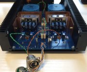
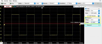
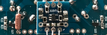
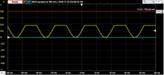
Build another F5-HA, while helping Patrick to test build the new board. Sq waves attached.
Everything is in order with the board. Picture showed the servo and MOSFET protection circuit. Scope shows the MOSFET current limiter in action, aggressive cutoff at 300 mV. I don't use the limiter, as such it was removed after testing of all sides.
MOSFET biased at 150mA, DC offset is < 5mV. As such I removed the servo to be used elsewhere. The importance of well matched devices 😉
Attachments
- Status
- Not open for further replies.
- Home
- Amplifiers
- Pass Labs
- F5-HA Build Thread