did you tried fat bridge between two channel PCB GND (power) points?
I just did and no change. Then I connected input RCA ground and no change either.
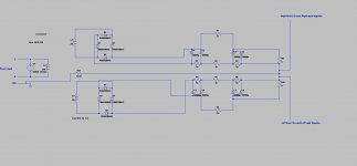
It's a bad drawing, it's the "ground" at the input RCA that's connected to Earth
As noted in the article you links to in post #1 "On professional and
commercial audio gear, the reason why RCA receptacles are always co-located on the
rear of equipment and why the interconnect cable left and right channels are bonded
together: it dramatically reduces the loop area and hence minimizes the opportunity for
noise ingress." This is something you could try to implement.
Last edited:
This is the one I linked to.
And not a bad drawing.
Patrick
.
My bad. Apologies.

Could you disconnect all the internal mains wiring and connect the primary directly to the mains so you have no mains current in the vicinity of the amplifiers or their inputs?
Also see pages 61-63 of the file
Also see pages 61-63 of the file
Last edited:
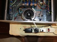
As Scott mentioned, keep the AC wiring away from the amplifier boards. My suggestion is to move the soft start board to the front left, next to the on-off switch. Route the AC from the inlet jack straight directly to the front of the case. It can probably fit under the perforated metal bottom plate. Keep AC away from the sides.
Also rotate the transformer. At some point you will find a position of least noise. My experience with Antek transformers is that the position of least noise is when the secondary wire output location is in the centre of the case next to the power supply board.
Very informative information by diyAudio member Bonsai:
http://hifisonix.com/wordpress/wp-content/uploads/2019/02/Ground-Loops.pdf
Lots of information with practical tips towards the end of the article.
It looks like your power supply output ground point is taken from the positive side ground. Try moving the ground point to the middle tie point or at least try connecting a big wire from the negative ground point to the positive ground.
This is the one I linked to.
And not a bad drawing.
Patrick
.
Here is a diagram of my grounding scheme,absolutely no hum, my F7 rendition
Attachments
Could you disconnect all the internal mains wiring and connect the primary directly to the mains so you have no mains current in the vicinity of the amplifiers or their inputs?
Also see pages 61-63 of the file
I realy had high hopes that this suggestion will work. Unfortunately, about the same level of hum was coming through the speakers.
Attachments
Last edited:
It looks like your power supply output ground point is taken from the positive side ground. Try moving the ground point to the middle tie point or at least try connecting a big wire from the negative ground point to the positive ground.
Negative of the positive side is connected with jumpers to positive of the negative side. I could change side, but if there is a problem here it would be created in opposite way. There are 6 jumpers in spots provided on the PCB.
As Scott mentioned, keep the AC wiring away from the amplifier boards. My suggestion is to move the soft start board to the front left, next to the on-off switch. Route the AC from the inlet jack straight directly to the front of the case. It can probably fit under the perforated metal bottom plate. Keep AC away from the sides.
Also rotate the transformer. At some point you will find a position of least noise. My experience with Antek transformers is that the position of least noise is when the secondary wire output location is in the centre of the case next to the power supply board.
Very informative information by diyAudio member Bonsai:
http://hifisonix.com/wordpress/wp-content/uploads/2019/02/Ground-Loops.pdf
Lots of information with practical tips towards the end of the article.
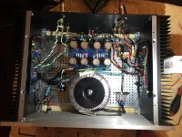
THIS IS IT! I rotated the transformer per your suggestion and hum is gone!
There is only slightest noise that I can only hear with my ear right next to the tweeter and only if the room is quiet.
The board in top right corner is not soft start but remote trigger and 12V for the switch LED. The switch is also wired with 12 VDC that turns on relay coil and passes 120 VAC trough contacts.
Thanks Again to everyone. Great suggestions. I tried most of them and you collectively solved another conundrum.
Thanks Ben Mah.
Attachments
What is the best way to adjust the P3 when already installed on the board?
Measuring and matching the resistance over R3 and R4 with amplifier off, or measuring and matching voltage over R3 and R4 when amplifier is on?
Measuring and matching the resistance over R3 and R4 with amplifier off, or measuring and matching voltage over R3 and R4 when amplifier is on?

P3 - a video by 6L6:
Adjusting P3 - a video
Also see "Setting P3" in post #1 if you are not fine tuning the distortion:
https://www.diyaudio.com/forums/pas...fier-illustrated-build-guide.html#post3973246
Last edited:
I'm glad you found the cause. It raises the question as to whether toroidal transformers are not the best option.
While biasing F5 I have noticed that values drift, in my opinion, significantly.
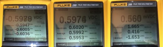
I have recorded for left channel over 90 seconds period NPN, PNP, and DC offset:
Min -594.7mV, Avg -600.5mV, Max -603.6mV.
Min 595.3mV, Avg 599.2mv, Max 602mV.
DC Offset Min -1.653mV, avg 0.416mV, Max 1.665mV.
Is this acceptable, good, or bad?
I have recorded for left channel over 90 seconds period NPN, PNP, and DC offset:
Min -594.7mV, Avg -600.5mV, Max -603.6mV.
Min 595.3mV, Avg 599.2mv, Max 602mV.
DC Offset Min -1.653mV, avg 0.416mV, Max 1.665mV.
Is this acceptable, good, or bad?
Attachments
that's hilariously good
you're not making instrumentation amplifier, that's Singing Owen
though, what you need to observe is Temp Equilibrium state - closed lids and amp on steady max temperature
so, observe from cold, and sharpen your screwdriver for 90min point
you're not making instrumentation amplifier, that's Singing Owen
though, what you need to observe is Temp Equilibrium state - closed lids and amp on steady max temperature
so, observe from cold, and sharpen your screwdriver for 90min point
- Home
- Amplifiers
- Pass Labs
- F5 Cross channel ground loop