What about using something larger than 1000uF for output cap?
I see you used 8200, like the MoFo amp.
I see you used 8200, like the MoFo amp.
You're right. I was checking the impact of the divider's cap on startup with very big caps.
Imo, 1000uF is more than enough for headphones. If you go bigger, you really need a muting relay to avoid too much current going through the headphones at start up.
If you want to use the amp with both headphones and speakers, I'd make two different outputs. One with 10.000uf for the speaker and one with 470u-1000u for headphones.
I'd make two different outputs. One with 10.000uf for the speaker and one with 470u-1000u for headphones.
That's good advice. Thanks!
I gathered all the part for this amp (HPA), but have a question before i start putting it together.
Using a 24v 6.8A SMPS for each channel. Where is the single negative signal of the headphones returned? I was going to send it to chassis, but thought that might generate noise.
I looked at other HPA designs and they all use a single supply. I want this amp to drive speakers as well, so I like the extra power availability.
Also, since it's a power follower, am I correct in assuming that a resistor to reduce output is not necessary?
Thanks,
Vince
I gathered all the part for this amp (HPA), but have a question before i start putting it together.
Using a 24v 6.8A SMPS for each channel. Where is the single negative signal of the headphones returned? I was going to send it to chassis, but thought that might generate noise.
I looked at other HPA designs and they all use a single supply. I want this amp to drive speakers as well, so I like the extra power availability.
Also, since it's a power follower, am I correct in assuming that a resistor to reduce output is not necessary?
Thanks,
Vince
What’s wrong with using the psu ground?
Thanks Hikari.
Probably nothing. Was going to try it anyway, if no answers but there's the whole symmetry thing since the headphones only have 1 ground and using two power supplies.
Probably nothing. Was going to try it anyway, if no answers but there's the whole symmetry thing since the headphones only have 1 ground and using two power supplies.
...Using a 24v 6.8A SMPS for each channel. Where is the single negative signal of the headphones returned?....I want this amp to drive speakers as well, so I like the extra power availability....
24v 6.8A ??

The "power" is totally determined by the 16r resistor. 24V/16r = 1.5 Amps ABSOLUTE MAX. Biased for audio, 1.0 Amps per channel, 2A for both.
Making more current available to the resistor will NOT change the power you can get out of it.
Using a single 6A supply, it will loaf, the circuit gets all it can eat, and you avoid the question of how to connect two supplies.
Anyway if you wanted "power availability", you would not use this circuit and not with these values. The Resistance-Loaded power amplifier is most *efficient* with RL = 1.4 times load. For 8 Ohms, use 11 Ohm resistor. Bias to 16V-17V at Source. 3W/ch with 36W/ch dissipation.
If efficiency be dammed, Voltage is fixed, current is free, then you make RL "small". In small-signal work we might make RL 1/10th of the load being driven. Say 1 Ohm. HEAT rises faster than power output, but damm the efficiency. Ah, bias to about 13V, that's 13 Amps, bigger than your supply. Try 4 Ohms, a fair compromise. Bias a hair over 13V, 3.3A per channel, so two channels can sip from one 6.8A supply. (I'd round-up to 5 Ohms so the supply is not AT rating.) Now you have 7W/ch with 80 Watts dissipation/ch.
Headphone common return is not a big deal here. The amp has no voltage gain and the 16r RL swamps load current.
PRR,
Sorry you had to write that all out.
I'm sure I used the wrong words when describing what I'm doing.
I chose a higher current SMPS so it would be under less stress.
The price difference between a 4A and a 6A is small.
I like dual-mono in one case.
Thanks for the explanation.
Vince
Sorry you had to write that all out.
I'm sure I used the wrong words when describing what I'm doing.
I chose a higher current SMPS so it would be under less stress.
The price difference between a 4A and a 6A is small.
I like dual-mono in one case.
Thanks for the explanation.
Vince
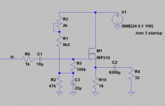
Should there be a resistor at the gate of the mosfet in this schematic?
I put in a 100 ohm since it's often recommended.
Not getting any sound, but the voltages look OK.
Wondering if the gate resistor is causing it.
Did I make a voltage divider?
I put in a 100 ohm since it's often recommended.
Not getting any sound, but the voltages look OK.
Wondering if the gate resistor is causing it.
Did I make a voltage divider?
Attachments
Last edited:
Got it working. I joined a point in the circuit that was not in the new schematic. The 5k works ok. Able to adjust voltage center point. Also left in the 100 ohm resistors on the gate.
Attachments

Last edited:
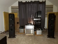
Immediate impressions are very good. Despite my usual sloppy wiring, its quiet.
This little amp has a soul. The detail pours out of it. Its layered.
Solid imaging beyond the speaker edges , depth is pretty good.
Its driving an 87db sensitive 6 ohm speaker, but its hanging in there.
There's also the nice impact you get from power followers, like it has more power than spec'ed. There is a turn-on thump.
I can sense distortion in the highs, but it's because I'm driving it a bit hard and using rock music. Has a sweeter quality with jazz and softer music. Highs might be rolled off some but not really missing anything.
Using:
irfp150n mosfets
Mostly generic metal film resistors, except a couple PRP resistors.
Mills aluminum housed power resistors.
8200uF Elna caps that I had pulled from a reciever 25 years ago.
PVC copper wiring.
Generic input and output connectors
24v, 6.7A smps power supply.
Hifi2000 case
Don't sleep on this one if you want/need a good, simple amp you can build over a weekend or two. It's also a good intro into power followers with no exotic parts. Heat sinks are small yet its only warm to the touch. Oh yeah, and it's supposed to be a headphone amp. 😉
Thanks for the help!
Vince
Attachments
Last edited:
Hey Scott. I haven't switched them up yet, but it does have resemblance to the MoFo. The MoFo does have 4x the power. The F7 is something altogether different. I might prefer the MoFo to the F7, especially if I'm in the mode to be lied to and beguiled. 😉
Stop over for a listen to all three. 😀
best,
Vince
Stop over for a listen to all three. 😀
best,
Vince
Ran power measurements on the F5HPA and it puts out a little more than 1w RMS of clean power and 2w RMS with some distortion of the wave form on negative phase peak.
Not that I have ever purposefully listened to a 1w amp before, but being this is a first for me, 1w is a lot of power! 😀
Not that I have ever purposefully listened to a 1w amp before, but being this is a first for me, 1w is a lot of power! 😀
Ran the amp as a headphone amp tonight.
Doesn't require high gain preamp.
Volume position at 9 o'clock.
I'm not really a headphone guy and don't have really good headphones (Grado SR-60), but it sounds fine... 🙂
Doesn't require high gain preamp.
Volume position at 9 o'clock.
I'm not really a headphone guy and don't have really good headphones (Grado SR-60), but it sounds fine... 🙂
I read PRR`s post #30 two or ten time. 🙂
Settled for an 8 ohm 100w resistor on the mosfet source.
Left it at 16v. I calculated 5w output.
The sound is still engaging, and now has a bit more headroom.
Still better with simpler music.
Runs hotter, but can hold hand to heatsink for more than 10 seconds.
It is winter...
Settled for an 8 ohm 100w resistor on the mosfet source.
Left it at 16v. I calculated 5w output.
The sound is still engaging, and now has a bit more headroom.
Still better with simpler music.
Runs hotter, but can hold hand to heatsink for more than 10 seconds.
It is winter...
- Home
- Amplifiers
- Pass Labs
- F5 Article Headphone Amp