
Is the 16 ohm resistor rated at 16W?
16v through 16 ohms is 1 amp? 1A x 16v=16w?
Yes, plus a safety margin. This circuit is class A, so there is
considerable quiescent power dissipation.
Last edited:
dissipation P=I^2 x R
P=1A^2 x 16=16W
use 50W chassis mount thingie , no less than that
dirt cheap on fleabay - those Goldie ones
or buy brand name , for more money
P=1A^2 x 16=16W
use 50W chassis mount thingie , no less than that
dirt cheap on fleabay - those Goldie ones
or buy brand name , for more money
Can get some Mills wire-wound 12 or 18 Ohm for 25% off.
Would 12 ohm or 18 ohm throw off the design?
Since I want to get a couple good caps from this store, I would like to buy from once place.
Thanks,
Search Results for: aluminum resistor
Would 12 ohm or 18 ohm throw off the design?
Since I want to get a couple good caps from this store, I would like to buy from once place.
Thanks,
Search Results for: aluminum resistor
18 is close enough
though , note that you need to establish some kind of biasing fine setting ....... besides having sensible matched pair of IRFP , for two channels
though , note that you need to establish some kind of biasing fine setting ....... besides having sensible matched pair of IRFP , for two channels
note that you need to establish some kind of biasing fine setting
I was wondering if 10k or 47k was providing bias or both acting as voltage divider?
They are not feedback, are they?
Could I use a 50k trim pot instead of a 47k fixed?
no feedback in classic way , because there is no significant series impedance in gate...so biasing voltage divider
better use 8K2 in series with 5K pot (connected as variable resistor) , instead of 10K
though = you need that only if you want to tweak Iq
if not , everything as is , use matched mosfets and you'll have same Iq in both channels , slightly smaller than 1A
better use 8K2 in series with 5K pot (connected as variable resistor) , instead of 10K
though = you need that only if you want to tweak Iq
if not , everything as is , use matched mosfets and you'll have same Iq in both channels , slightly smaller than 1A
Last edited:

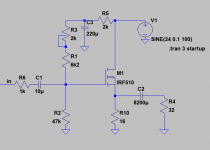
Before I posted #7, I looked at MoFo schematic because it uses feedback. Wanted to see how it used the trim pot.
Feedback not really used in followers?
BTW- can build this amp for a few dollars if you already have a couple mosfets and a 24v high current computer power supply.
I have a 24v 8A supply waiting for a job.
Feedback not really used in followers?
BTW- can build this amp for a few dollars if you already have a couple mosfets and a 24v high current computer power supply.
I have a 24v 8A supply waiting for a job.
Last edited:
well , source follower is all feedback ........ so whatever you do from drain , where there is steady DC and zero AC , you can't induce any feedback
remember that guy from Yore , having enormous Lever , but no one gave him standfast , so he couldn't move Earth
there is no standfast for feedback on drain
and yes - this thingie is same as Mofo..... just having big fat resistor instead of choke
remember that guy from Yore , having enormous Lever , but no one gave him standfast , so he couldn't move Earth
there is no standfast for feedback on drain
and yes - this thingie is same as Mofo..... just having big fat resistor instead of choke
...Is the 16 ohm resistor rated at 16W?...
It *dissipates* 16 Watts, yes.
If you build cheap and sell on 30-day warranty, a 16W rating may be good enough (but a fire hazard).
For yourself, *always* double the dissipation then round-up generously when you shop. A 25W sand resistor really is not enough. The "50W" chassis-mount only do 50 real Watts on a HEAVY chassis or honest heatsink. Myself I'd look for four 10W 64 Ohm sand-resistors and some hi-temp lug-board. I have used 25W chassis-mount at 4W each on a heavy chassis (special case: home heat fan controller, and I don't want it to fail on a bad day).
I do appreciate the advice and teachings.
I really do. However, in my own defends, if my calculation was correct, which it was, but used incorrect equation to get there, I would have used the next highest value wattage. Here's why.
The Son of Zen article. It's says, unlike the mosfets, you can run power resistors closer to their power rating. I don't even have to look it up. I remember it.
This is why guys like me get confused and ask questions all the time. Despite seeming like rules, things in electronics seem more like moving targets.
Seriously, thanks again.
I already bought 50 watters.
Vince
I was wondering if 10k or 47k was providing bias or both acting as voltage divider?
It's actually a rather poor way of providing bias (that schematic isn't full fledged, it is there for illustration). It will inject the PS noise at the input. It would be better to run a divider with a 22uF cap in // with the bottom resistor and take the bias from there through a 100k resistor.
It will also limit the start up thump from the output cap by slowly ramping up the bias.
Last edited:
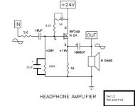
Vince - this would be a great opportunity to try an inductor instead of the resistor, I.E., build it as shown and then swap out the source resistance for a choke and make it a MoFo. See which sounds better.
build it as shown and then swap out the source resistance for a choke and make it a MoFo. See which sounds better.
Have a set of 193v that need a job. 😀
Want to try this amp as both a headphone amp and speaker amp.
I'm not a headphone guy, but doesn't hurt to have one around. 🙂
More like this.
This being said, the cap might not be actually necessary with a switching PS; some are very quiet at audio frequencies, even under heavy load. But some headphones are also very sensitive...
Another possibility is to do it like Pete Millet did it for his hybrid, by adding a RC filter before the bias divider.
Attachments

Last edited:
- Home
- Amplifiers
- Pass Labs
- F5 Article Headphone Amp