vdi, those are some professional looking heatsinks too - nice job! That looks like fun day of bi-amping/testing there as well 🙂
Cheers again all!
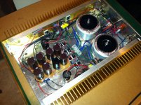
My brother cut every fin and separator on a mill. No saw cuts. 🙂
If it matters, I switched out the L'amp CSS with the Zen 9 (a.k.a F3) last night. The Zen 9 is a fantastic amp and worth the effort. The sound has a nice body to it. Fleshes out voices and instruments very well. Very much like attending a recording session. The SIT CSS (5w) is a bit more like being in the room with musicians, but with a bit less headroom. Does great with simple music. The Zen 9 has a bit more guts. Real fun to listen to the Zen 9.
Using it to drive a 6.5", 95db full-range driver. Surprising amount of bass and control for 15w.
Don't use an IEC line filter, like I did. It was a mistake.
Also, I didn't use the 15 Silmic II 1000uF caps for the output cap. Used 1 larger Mundorf and by-pass it with 2 Silmic II caps instead.
Ultimately, the 15 Silmics II would be better, but I think what I configured sounds fine. It's cost thing. 😉
Good luck!
Attachments
Last edited:
Thanks for the encouragement!
Thanks for your comments on the F3 sound :0 I'm certainly looking forward to getting it done and having a good listen. The gold heatsinks on there are nice for a bit of bling 😎
I'm personally striving towards the logical conclusion of the Pass philosophy - a single gain stage pre (B1 or a JBOZ), a single gain stage power amp (F3 clone) driving a set of full rangers (Cain and Cain Abbey Clone).
I'm just curious to see how that sounds as a set up. It seems like the logical conclusion; you get two inversions of phase (Jboz), a minimal number of parts in the signal chain, and pretty minimal feedback as well. All driving the simplest of speakers.
I for one cant wait, so please have a good listen and enjoy that system you have there!
PS - I'm jealous of your L'amp - I quite enjoyed the article about the L'amp but I'd say the odds of ever ending up being in possession of the SIT's is quite close to zero these days!
The gold heatsinks on there are nice for a bit of bling
It's what I could get my hands on at the time.
...single gain stage power amp (F3 clone) driving a set of full rangers (Cain and Cain Abbey Clone).
I'm sure it will sound great! Just try to get the absolute phase correct.
being in possession of the SIT's is quite close to zero these days
Why do you say that? Never say "never"!
minimizing distractions
In fairness I should probably properly finish what I have already got. Then I can allow myself the next interesting thing that has caught my eye.
I'm shocking for getting all the hard/interesting bits done and then moving on the the next project...
In fairness I should probably properly finish what I have already got.
Then I can allow myself the next interesting thing that has caught my eye.I'm shocking for getting all the hard/interesting bits done and then moving on the the next project...
In fairness I should probably properly finish what I have already got.
Yes, that is more important than it sounds. Follow through.
Best,
Vince
A question.
I just finished measuring the Vgs on the Lu's I have and have a reasonable spread of valures. Is it better to have a higher Vgs or a lower for the F3 (or even does it matter?)
I just finished measuring the Vgs on the Lu's I have and have a reasonable spread of valures. Is it better to have a higher Vgs or a lower for the F3 (or even does it matter?)
Cheers Vince, thanks for the input.
I have indeed done so, and I have some low matches (.95 or so) and some higher (1.14).
I put the 1.05 match aside to use as it's easy to match to the graph, but it prompted the question (to extend my own learning) as to which would be better and why?
Edit - matches at 0.85, 0.9, 1.05, 1.07 Vgs. I appreciate that I dont need to match between channels, but I can, so why not?
Last edited:
Hi AndrewT, I do indeed, I I initially settled on the 1.05 Vgs pair as it makes for an easy resistor value for R3 (2R from memory).
I just wanted to know if there was a benefit/issue with some of the different values?
I just wanted to know if there was a benefit/issue with some of the different values?
oh no! an output capacitor question!
So, a question to set fire to the floor beneath me - how carried away on the output cap should I get?
I appreciate that the answer will be 'whatever makes you feel best', so I might cull the possibilities down a little.
1. fits on the board - a rubycon 10000uf 25V cap, a 47uf 25v ally case mystery brand electro, and a random polyprop (value from .1uf to .3uf depending). This is my current leader...
2. doesn't fit on board - elna for audio 63V 12000uf, and whatever combo of polyprop crossover cap(s) floats my boat at the time of building. Annoying to mount, but minimal extra fuss.
3. is ridiculous - a stack of 2200uf 35V kme(?) branded electros in parallel till I run out of space/caps/patience and a few 2.2uf (or 6.8uF) x2 polyprops as a garnish on top. Can do this easily enough, but I'm not sure about the value vs waste really.
I've a pile of 63V polyesters about as well; just to muddy the waters 🙂
So, a question to set fire to the floor beneath me
- how carried away on the output cap should I get?I appreciate that the answer will be 'whatever makes you feel best', so I might cull the possibilities down a little.
1. fits on the board - a rubycon 10000uf 25V cap, a 47uf 25v ally case mystery brand electro, and a random polyprop (value from .1uf to .3uf depending). This is my current leader...
2. doesn't fit on board - elna for audio 63V 12000uf, and whatever combo of polyprop crossover cap(s) floats my boat at the time of building. Annoying to mount, but minimal extra fuss.
3. is ridiculous - a stack of 2200uf 35V kme(?) branded electros in parallel till I run out of space/caps/patience and a few 2.2uf (or 6.8uF) x2 polyprops as a garnish on top. Can do this easily enough, but I'm not sure about the value vs waste really.
I've a pile of 63V polyesters about as well; just to muddy the waters 🙂
That's what I originally thought... But I came to doubt that was the case for the following reason.
PCB cap dimensions - The PCB shows a pitch of 10mm for the pins and a diameter of about 22mm. This seems to be backed up by what I have seen in photos on the web, as the size appears to match this pcb. I can't find a 50V 15000uf cap anywhere that is that diameter.
The closest I can see is THIS and thats a 35V 10000uF part.
Can anyone say what the original part in the Firstwatt F3 was?
All of this is potentially a moot point - I have suitable caps I can use, but not that fit on the PCB, and I'm not understanding what would have been used 'officially'. Can you point me at the cap in question?
it's 15mF/25V in original
think - what's voltage across cap when amp's output is , say , at peak of positive sine ....... and what's voltage when amp is in idle ?
think - what's voltage across cap when amp's output is , say , at peak of positive sine ....... and what's voltage when amp is in idle ?
Having a bit of a punt about it - Nelson seems to use 25V 15000uF parts in the power supplies of all things firstwatt, and they do seem to look uncannily like the parts you can see in most of the firstwatt f3 pics on the web.
Just saying...
Just saying...
Oh Hi ZM! You answered whilst I was typing 🙂
Thanks for the reply - that thought is where I'd got to when I asked the original question! As I understand it at no signal, you have about 21V on one side of the cap, and 0V on the other. At peak you have 21+peak on one side and 0V + peak on the other... A difference of 21V. Or am I missing something? Almost every other thread on the F3 has a 50V part reccommended for C1...
Thanks for the reply - that thought is where I'd got to when I asked the original question! As I understand it at no signal, you have about 21V on one side of the cap, and 0V on the other. At peak you have 21+peak on one side and 0V + peak on the other... A difference of 21V. Or am I missing something? Almost every other thread on the F3 has a 50V part reccommended for C1...

- Status
- Not open for further replies.
- Home
- Amplifiers
- Pass Labs
- F3 Clone Build - building own heatsinks