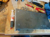
One way of making DIY heatsinks is to cut slots in the backing plate and to fit tight fitting fins into the slots.
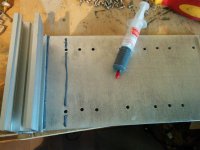
Another method is to make an aluminium sandwich of strips interleaved with larger fins.
The best method is to raid the bins on the industrial estate. Some industrial electronic invertors use huge heatsinks. Big companies just chuck them when they fail.
Another method is to make an aluminium sandwich of strips interleaved with larger fins.
The best method is to raid the bins on the industrial estate. Some industrial electronic invertors use huge heatsinks. Big companies just chuck them when they fail.
Last edited:
How are you planning on attaching the fins to the plate. I think I see two holes per fin so I assume with bolts. You should also use a thermal epoxy and these are expensive.
This is what I mean by Metal carbide cut off wheel
7 in. 40 Grit Metal Cut-off Wheel 5 Pc
Will this work to cut aluminum plate or will it get loaded and overheat?
This is what I mean by Metal carbide cut off wheel
7 in. 40 Grit Metal Cut-off Wheel 5 Pc
Will this work to cut aluminum plate or will it get loaded and overheat?
nashbap I have definitely had good results cutting aluminum using my table saw with a carbide tipped woodworking blade. Carbide is a lot harder then aluminum so no problem.
Evan
Evan
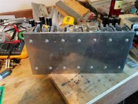
Hi Nashbap - I'd second the table saw option. I've almost always got a nice neat cut that way. With regards to fixing them on to the plate, I'll be using screws and I've some large supplies of thermal paste to thermally bridge between the fins and plate. I've a wee bit of sanding flat to do as well to make the best possible contact between the two.
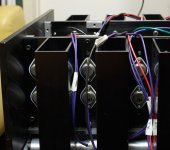
Thanks for that photo vdi_nenna - thats the heatsink that gave me the idea originally - although I've not seen that shot of it. Looking again those box sections are a lot meatier that the extrusion I have to play with. That said, I'll be using a few more.
I was a bit disappointed yesterday, thinking that the end result wouldn't do the job, but today I feel a bit more positive and I might try finishing them off, and then doing a moderately scientific test of their thermal capacity...
nashbap I have definitely had good results cutting aluminum using my table saw with a carbide tipped woodworking blade. Carbide is a lot harder then aluminum so no problem.
Evan
Thanks. I'll give it a go with a thin kerf carbide toothed blade.
I was a bit disappointed yesterday, thinking that the end result wouldn't do the job, but today I feel a bit more positive and I might try finishing them off, and then doing a moderately scientific test of their thermal capacity...
There are obviously loads of ways of pumping heat into the sink to see how well it gets rid of it but the easiest method is probably with a high power resistor or two.
Up and running
Well after a bit more drilling, chopping and about 30grms of heatsink paste I had something to test.
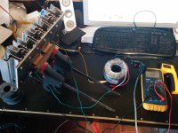
I jury rigged up a test jig and applied power for about 20 minutes (not enough) before one of the clip leads' shrouding started smoking 😀 so I pulled the power at that point. End result (from a starting temp of 17C) was the heatsink body at about 40C just near the power resistors.
This is in no means conclusive, but I feel a lot happier.
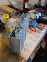
I've become a bit dubious about my sanding job on the ally extrusion - I hit it with 320grit paper for a while and moved on to screwing everything on, but one of the later bits looked like I'd only got through the coating at the corners... This implies that I didn't get through the coating on any of them 🙁 I'll try it as is, and if it's no good then at least I know where I can get some improvements.
I'm considering cutting a bit of an angle on the top and bottom to make it look a little less brutish - and it'll hide where the job slipped about on the table when cutting the extrusions. I'll need to work out -how- to do that though 🙂
Apologies for the res of the attached pics - I had the camera turned back up to full res. (fixed!)
Well after a bit more drilling, chopping and about 30grms of heatsink paste I had something to test.
I jury rigged up a test jig and applied power for about 20 minutes (not enough) before one of the clip leads' shrouding started smoking 😀 so I pulled the power at that point. End result (from a starting temp of 17C) was the heatsink body at about 40C just near the power resistors.
This is in no means conclusive, but I feel a lot happier.
I've become a bit dubious about my sanding job on the ally extrusion - I hit it with 320grit paper for a while and moved on to screwing everything on, but one of the later bits looked like I'd only got through the coating at the corners... This implies that I didn't get through the coating on any of them 🙁 I'll try it as is, and if it's no good then at least I know where I can get some improvements.
I'm considering cutting a bit of an angle on the top and bottom to make it look a little less brutish - and it'll hide where the job slipped about on the table when cutting the extrusions. I'll need to work out -how- to do that though 🙂
Apologies for the res of the attached pics - I had the camera turned back up to full res. (fixed!)
Attachments
Last edited:
Thanks Katieanddad - thats pretty much the way it went. The resistors were a pair of 4.7R 50W items, and the torroid is a 60V secondary with a center tap - I used it as a 30VAC source and it sagged to about 27VAC; so I make that to be about 75W through it.
I'm thinking about using the same torroid for the actual F3 build. That'd reduce the heat dissipation burden somewhat, and I've two of them handy... Reduced total output power isn't an issue as it'll be driving a pair of abbey clones.
Edit - Oh, and ZenMod, thanks for the input. I added the additional fins as suggested. Thanks!
Last edited:
Next challenge is how to mount the LU jfet. I'm scrambling through the junkbox for a separate heatsink for this jfet - shes doing all the actual work so surely she deserves something nice? 🙂
On the other hand, a couple of flying leads is certainly easier...
On the other hand, a couple of flying leads is certainly easier...
not separate .... it's natural that LU is on same heatsink with it's own cascode
in FW F3 , LU is mounted on back side of heatsink bar , metal tab up and soldered ditto in bottom copper side of pcb
mounting via clamp
look at pics on 6moon , you'll see LU , through custom hole in pcb , near input
look at pic , red top , green bottom coper ...... blue circ hole
in FW F3 , LU is mounted on back side of heatsink bar , metal tab up and soldered ditto in bottom copper side of pcb
mounting via clamp
look at pics on 6moon , you'll see LU , through custom hole in pcb , near input
look at pic , red top , green bottom coper ...... blue circ hole
Attachments

Last edited:
Hi Zenmod. My problem is the 'backside' of my heatsink is the 'outside' 😀
I'm going to try and manage without a heatsink bar and just mount everything directly to the heatsink surface - and the best solution I can think of is a couple of lying leads to the LU so I can turn it over and have it facing the same way as the big fets. It just feels a bit like an ugly solution. 🙁
I'm going to try and manage without a heatsink bar and just mount everything directly to the heatsink surface - and the best solution I can think of is a couple of lying leads to the LU so I can turn it over and have it facing the same way as the big fets. It just feels a bit like an ugly solution. 🙁
Hi Bare,
Cheers for the link. It is indeed a viable alternative; we'll see how we get on with what I've made for now though. And in all honesty I'd probably start dropping the transformer voltage and reduce dissipation that way, rather than uprating the heatsinking.
On the other hand I got an answer back from Conrad about their biggest flanged heatsink, and it's not ridiculously expensive either; so there are options to follow up on either way should this not work.
I'm still a bit concerned with the spacing available on the pcb for an output cap - nothing I can find will fit. I've plenty of stuff on hand I can use however; again using flying leads.
I'm starting to think I should have made it a point to point build 🙂 Anyway, waiting on a few parts so there will probably be a bit of a delay before I get on with it.
One of our Members built up a pair of these successfully.
Lots of pics and details if you can find hi/her posts.
Between heatsink USA and Conrad, the USA and Australia are well covered for affordable heatsinks.
I built those heat sinks, but used them on a low powered Aleph.
Old pic.
Come to think of it, AndrewT is right. All that cutting is daunting. Raw aluminum isn't cheap unless you get it at a salvage yard, but still has a price.
Your time might be better suited elsewhere. At heatsinksusa.com, you can get a 10"x8"x2" heat sink for $50.
Attachments
Last edited:
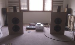
vdi, those are some professional looking heatsinks too - nice job! That looks like fun day of bi-amping/testing there as well 🙂
AndrewT - I agree with your comment on the Conrad sinks - I can get a pair delivered that might just do the job for about $100. This was an exercise in using what I had available, and if nothing else, I do have a pair of heatsinks now for another project in the future. 😀 Given that tends to be the big expense for me I'll call that a win whatever happens.
Cheers again all!
- Status
- Not open for further replies.
- Home
- Amplifiers
- Pass Labs
- F3 Clone Build - building own heatsinks