Hi all,
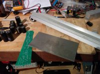
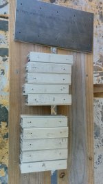
I've a bit of time off at the moment, so what better to do than finish the F3 clone I've wanted to do for ages? I'll be using some suds pcb's and pretty much what I have on hand for components
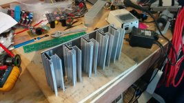
I'm a bit of a cheapskate, so for this build I'll be making my own heatsinks. Using a slab of 150x300mm 5mm think plate, and a bunch of offcuts from some solar panel rails as 'fins' I hope to end up with something that's good for the job.
I anticipate some 'challenges' one of which is that I believe that the ally rails I'll be using have a coating on them. I can obviously sand that off, but part of me is wondering about anodizing all the parts as well... I happen to have some fancy anodizing dyes I bought ages ago (and never used) so I could make this quite a garish colorscheme 🙄
Anyway, here's a quick photo of the boards and ally.
Edit: I'll reduce the resolution of future photos...
I've a bit of time off at the moment, so what better to do than finish the F3 clone I've wanted to do for ages? I'll be using some suds pcb's and pretty much what I have on hand for components
I'm a bit of a cheapskate, so for this build I'll be making my own heatsinks. Using a slab of 150x300mm 5mm think plate, and a bunch of offcuts from some solar panel rails as 'fins' I hope to end up with something that's good for the job.
I anticipate some 'challenges' one of which is that I believe that the ally rails I'll be using have a coating on them. I can obviously sand that off, but part of me is wondering about anodizing all the parts as well... I happen to have some fancy anodizing dyes I bought ages ago (and never used) so I could make this quite a garish colorscheme 🙄
Anyway, here's a quick photo of the boards and ally.
Edit: I'll reduce the resolution of future photos...
Attachments
Last edited:
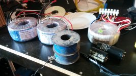
Psu
Next consideration is the power supply.
CRC (or even a cheapass version of CLC if I go the single power supply route)
I've a couple of 300VA-500VA torroids around with 30 - 35V secondaries, but with primaries at 220 - 240V. I've heaps of 50V caps, a few 63V caps and a couple of scavenged coils/inductors so parts for either approach is no problem.
The big blue thing is a brake coil from somewhere. Should I use it as the L in a CLC...
After dithering a while, I reckon I'll do a CRC PSU, and try and make sure the C after the R is getting less than 50V and pile the capacitance on. Failing that I'll extract a couple of the 63V Elna's from another project.
It'll all be point to point wired as I don't have any pcb's suitable here.
Edit - just remembered there's a 35 secondary, 235 primary 500VA torroid in an unfinished project. I reckon that'll be a great transfo for this project.
Attachments
Last edited:
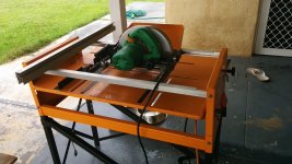
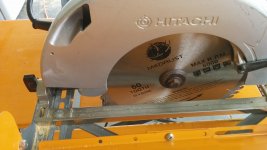
Cutting and drilling parts
Got the table saw out, put the best blade i had on it and started cutting ally up for fins.
Got them all marked out and drilled as well, and hopefully I've not made an **** out of my measurements...
I had an assistant to help - I just wish she had opposable thumbs...😱
Got the table saw out, put the best blade i had on it and started cutting ally up for fins.
Got them all marked out and drilled as well, and hopefully I've not made an **** out of my measurements...
I had an assistant to help - I just wish she had opposable thumbs...😱
Attachments

Last edited:
The only problem with the thin aluminium box section is heat transfer.
There's not a lot of meat to transfer the heat away from the backing plate.
Now, that back plate doesn't look like aluminium to me. If it's mild steel it wont work too well as a heatsink.
There's not a lot of meat to transfer the heat away from the backing plate.
Now, that back plate doesn't look like aluminium to me. If it's mild steel it wont work too well as a heatsink.
Got the table saw out, put the best blade i had on it and started cutting ally up for fins.
Got them all marked out and drilled as well, and hopefully I've not made an **** out of my measurements...
I had an assistant to help - I just wish she had opposable thumbs...😱
What blade did you use in the table saw?
Hi KatieandDad,
Yup, I hear you alright. I wasn't too sure about it either, but at the end of the day if the heatsink isn't up to it, I can use it elsewhere.
The 5mm stuff is definitely ally, it has some kind of coat on it as well it seems, so I'll need to clean that off as well. I'm just looking at how hard anodizing is likely to be, and if I can source the chemicals required... If I do that then a caustic soda bath will do it!
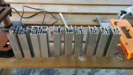
saw blade
Ni Nashbap,
Please see below. I've previously used a 40T blade but got a cheap 60T for todays effort. The actual ally ones are 80T. I take my time and it came out OK. Not perfect sadly, so if I commit to doing a great job I'll be filing away for a while...
Ni Nashbap,
Please see below. I've previously used a 40T blade but got a cheap 60T for todays effort. The actual ally ones are 80T. I take my time and it came out OK. Not perfect sadly, so if I commit to doing a great job I'll be filing away for a while...
Attachments
Hmm, turns out I can buy the chemicals I'd need for lots of anodising for about $70. I'll have to think about that one a bit, as I'll need to build a anodising power supply as well - and it looks like it'd need to push out about 6-8 amp. Again, I have the parts to build that too, but it's starting to get a bit big on me here...
http://astro.neutral.org/anodise5.shtml is what I'm looking at with regards to anodising information.
http://astro.neutral.org/anodise5.shtml is what I'm looking at with regards to anodising information.
Last edited:
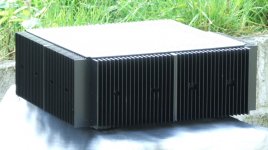
KatieandDad - yup that's a lot of heatsinking 🙂. Whats the F4 dissipation and whats the dimensions there on yours? I ask as I've a couple of f4 boards squirrelled away as well...
Last edited:
will it or wont it
I've built an F5 clone previously, and it did OK with a set of 300 x 80 x 60 (?) Conrad heatsinks with rather a lot of airflow and slightly reduced bias. As I see it the dissipation of the F3 shouldn't be too different, so worst comes to worst I'll pull a set of the same heatsinks off an older project of mine and sub these ones on.
If nothing else, they'll look pretty unique!
Attachments
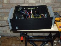
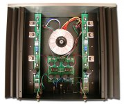
...And I just realized that the suds board is built for a 20 or 25mm diameter output cap. All the options I have here are somewhat larger in diameter.
...Come to check there aren't any matching the brief to be found at element14. What was used in the original if I may ask?
...And looking at the attached pic, which way around is the LU mounted? Looking at it it's 'upsidedown' relative to the other Fets? I'll trace out the circuit, but that's a new one on me!
Attachments
Last edited:
Ni Nashbap,
Please see below. I've previously used a 40T blade but got a cheap 60T for todays effort. The actual ally ones are 80T. I take my time and it came out OK. Not perfect sadly, so if I commit to doing a great job I'll be filing away for a while...
Are you saying that the 40T blade worked well?
Have you tried a metal cutting disc Some say it works fine others that it loads up easily cutting aluminum. I am asking since I need to be cutting some previously purchased heatsinks in half and not sure what to use. Since you have some experience with this what do you advice? Thanks.
......
If nothing else, they'll look pretty unique!
increase their number per side
squeeze in as much you can
Hi there ZenMod,
I can fit two more 'fins' per side assuming I can rustle up the extrusions to make em. I need to calculate the potential efficiency I think, as it looks like I'll need to buy some ally L angle to make a flange as well. I suspect I'm approaching the point where it might make more sense to buy a pair of these Conrads
I'm still quietly hoping that someone can confirm the capacitor used on the output of the f3 on a suds clone board. Diameter on the pcb is about 22mm, and I'll be stuffed if I can turn up a 15000uf 50V cap of that diameter anywhere... I've been browsing about and I'm getting the impression that the cap used originally was a 25V unit. Surely not?
Nashbap - when you say metal cutting disc, do you mean a cutting disc on a grinder? or do you mean a coldsaw? If you've access to a coldsaw, that'd be preferable. However I once wandered into a workshop where all they did was chop up ally extrusions and the used a standard circular saw with what looked like a 40T equivalent blade.
I'd say use what you have on hand and be slow about it. I have managed to forget I was cutting ally and tore a few teeth off the blade and bent the job quite badly. I spent a couple of seconds reassuring myself I still had the same number of fingers... 🙂
I'm at work at the moment so I'll try to describe this in words.
If you consider the semiconductors as taps supplying a constant supply of water to the sink.
The backing plate then becomes a bath that quickly fills up with water.
If all the aluminium was hollow, ie actually made to the same outside shape and dimensions of the heatsink but with paper thin walls.
The fins of the heatsink could then also be considered as part of the bath able to fill up with water.
Now, if you drill the entire surface of the tin foil heatsink with tiny holes the water can now escape.
Using this idea you can see how the semiconductors are heating up the aluminium and how the heat is trying to escape. Very thin aluminium heat paths will only allow a small heat flow.
tipping over the edge of sanity
Hi KatieandDad,
I do indeed get the analogy - the ally extrusions have approximately 2 x 1mm or so bits of ally conducting the heat outward to the extremity of the extrusions from the base. This is the main 'bottleneck' of the heatsink structure. With 5 'fins' per side as it is currently, that makes for 10mm x 150 mm per heatsink to conduct the heat away from the base. This is marginal (at best!). I can up that to 14mm x 150mm by adding two additional 'fins' (40% improvement?).
But will it be enough? Stuffed if I can judge, so the answer is to build it and see. 🙂
I kind of have a crazy plan in the back of my mind as a last resort. Melting aluminium from cans is moderately easy. Perhaps I can fill the voids in the extrusions with that? 😱
That'd sort the issue out nicely... Although where I'm getting to now is that it seems like a lot of effort to save $60!
Attachments
Last edited:
As a comparison I'm running the f5 clone I built a while back and seeing how hot it gets.
It's using the conrads I can get (easily) 300 x 75x 60 mm in size, and it's pushing about 40C over ambient at (from memory) about 1.2A bias, so about 60W. Meaning for 100W for an f3 (pessimistically!) I need about twice the heatsinking.
I'm thinking the homebrew heatsink isn't going to cut it... 🙁 And neither will the conrads I can lay my hands on.
Hmm, I didn't really want to use fans, so I guess a quote from Conrad is going to have to happen.
- Status
- Not open for further replies.
- Home
- Amplifiers
- Pass Labs
- F3 Clone Build - building own heatsinks