Hi,
I just put my name on the wiki for 1 stereo pair of F3 boards.
I also put my name in for 2 PS boards. Is this the right number of PS boards if I want to have one PS board for each channel?
I look forward to the group buy.
Thanks,
KT
I just put my name on the wiki for 1 stereo pair of F3 boards.
I also put my name in for 2 PS boards. Is this the right number of PS boards if I want to have one PS board for each channel?
I look forward to the group buy.
Thanks,
KT
KT said:Hi,
I just put my name on the wiki for 1 stereo pair of F3 boards.
I also put my name in for 2 PS boards. Is this the right number of PS boards if I want to have one PS board for each channel?
I look forward to the group buy.
Thanks,
KT
For F3,
I think you can just break think the Power supply in half here, as it's plain C-R-C. The F4 needs a v+ and v- power supply. so can upwards of two power supplies for one amp.
I beleive the PS in Firstwatt site is wrong, but I am not sure. I think 35v tranny to CRC will give ~45 volts. the 18v +18v is near the same, but I dont think 25v caps works here.
Balanced F4
4 total or order 2 pair....
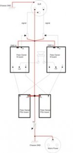
This pic from Adrej helped me with star grounding and understanding the balanced setup of the F4. I am not sure if we can do the same thing to F3. I presume not.
Adrej uses an attenuator in there, so assume just from signal to in. XLR pin 1 to right, Pin 2 to left, Pin 3 to ground.
khundude said:How many F4 boards do I need for a balanced amp?
4 total or order 2 pair....
This pic from Adrej helped me with star grounding and understanding the balanced setup of the F4. I am not sure if we can do the same thing to F3. I presume not.
Adrej uses an attenuator in there, so assume just from signal to in. XLR pin 1 to right, Pin 2 to left, Pin 3 to ground.
Attachments
Re: Balanced F4
if you want balanced F3 - then build SUSY F3 - thread is somewhere around
mithomas said:
4 total or order 2 pair....
This pic from Adrej helped me with star grounding and understanding the balanced setup of the F4. I am not sure if we can do the same thing to F3. I presume not.
Adrej uses an attenuator in there, so assume just from signal to in. XLR pin 1 to right, Pin 2 to left, Pin 3 to ground.
if you want balanced F3 - then build SUSY F3 - thread is somewhere around
Balanced F3
True, True -
ZM, you can kill the horse possibly on this.
Can we use two F3 amps to make balanced F3, or is it only possible with some sort of related negative rail thing?
😕
Yes, I plan on Susy F3 thingy as soon as someone else agrees first to build it.😀 Also thinking about LU head amp vis EUVL as well - something for work.
mithomas,
The pic of the balanced setup for F4 is way to small, would it be possible to post a bigger one?
thanks,
John
The pic of the balanced setup for F4 is way to small, would it be possible to post a bigger one?
thanks,
John
Re: Balanced F3
as I said in related thread - you can make SUSY F3 without neg leg in supply , paying the price with implementing input caps ...........
and - yes - you can make one SUSY from one stereo F3 , just toss these redundant parts out , and solder few more as dead bug on heatsink
mithomas said:True, True -
ZM, you can kill the horse possibly on this.
Can we use two F3 amps to make balanced F3, or is it only possible with some sort of related negative rail thing?
😕
Yes, I plan on Susy F3 thingy as soon as someone else agrees first to build it.😀 Also thinking about LU head amp vis EUVL as well - something for work.
as I said in related thread - you can make SUSY F3 without neg leg in supply , paying the price with implementing input caps ...........
and - yes - you can make one SUSY from one stereo F3 , just toss these redundant parts out , and solder few more as dead bug on heatsink
MEGA-amp said:mithomas,
The pic of the balanced setup for F4 is way to small, would it be possible to post a bigger one?
thanks,
John
I tried, send me a PM, unless someone knows how to get around this.
mithomas said:
I tried, send me a PM, unless someone knows how to get around this.
Increase the longer dimension to be around 10" and than choose stronger compression in jpeg so that your file size is no bigger than 100k

AR2 said:Increase the longer dimension to be around 10" and than choose stronger compression in jpeg so that your file size is no bigger than 100k
Diagrams like that are much better saved as (low bit) gif. Better fidelity & (usually) smaller size.
I took the original jpg that was posted above at 60k, removed most of the jpg noise and saved it as a 17k 8 colour gif.
dave
Moving Forward
Pappa himself approves---
😎
Group buys are not a problem. If I have any change in my policies, I will announce it with plenty of lead time.
As I have said elsewhere, the efforts of Rawson don't steal business from me per se, rather they drag down the reputation for quality that I try to maintain. np
So word of advice, dont try to sell on open market.
Alright then. Let's wait untill the end of the week. I will order 100 pcs of each amp board, unless the numbers increase.
Of course it's possible. This is how it goes: as soon as I order the boards I will announce payment info and boards will be sold on first come first serve basis; the Wiki page is only to give me an idea how many to order.
Re: F3 bom
Many thanks to Peter Daniel and to Mike for organizing the board reissue. Now that it looks like boards will become available, does anyone have a BOM for the power supply PCB? The BOM included in Mike's post only has components for the First Watt power supply which is a bit different than Peter Daniel's PCB. Recommendations for manufacturers and part nos. are greatly appreciated.
Thanks
mithomas said:This isn't for Mouser part #'s, but this will give you an idea.
I am not sure how the PS is being rigged in this design. I plan on F2 like Power supply using 35v transformer, and 50v+ caps, .47R resistors. Also the Fuse looks like this BOM suits 220v, which is fine for your area, I believe.
Matched MOSFETs are available from tech-diy.com
Many thanks to Peter Daniel and to Mike for organizing the board reissue. Now that it looks like boards will become available, does anyone have a BOM for the power supply PCB? The BOM included in Mike's post only has components for the First Watt power supply which is a bit different than Peter Daniel's PCB. Recommendations for manufacturers and part nos. are greatly appreciated.
Thanks
- Status
- Not open for further replies.
- Home
- Group Buys
- F3 and F4 Clone PCB Reissue group buy, also F5 PCBs