Hi all,
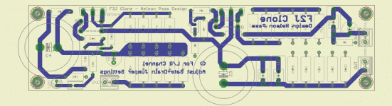
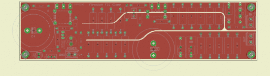
I just designed a F2J PCB, it is 200mmx50mm and has features such as:
- extra power resistor placements at the output and Vin for flexibility on setting the idle current and damping factor
- Flexible capacitor grid spacing
- a Jumper setting for Left and Right channels (which allows the use of single PCB design for both, and that I'm very proud of 😀)
I have 2 questions
1) is there any drawback using the same PCB for left and right channels (which will of course require flipping the PCB upside down and components placement on TOP and on BOTTOM depending on the side) ?
2) on the ground layout... I've read somewhere that ground planes can be a problem on Power amps if components are not properly placed... in that case which layout would be preferrable : just a simple ground plane, or one that separates INPUT and OUTPUT grounds by the means of a split in the ground plane ? (or any other ground layout??)
(NOTE: Input is on upper right, OUTPUT lower right, Power on bottom left)
PS: although I did extensive reading on the topic, I admittedly did not yet fully understand the grounding rules ... in France we have a saying that says "what is well conceivable can be clearly explained" but grounding layout to me is an exception and still pretty unclear...
Attachments
Last edited:
Noone on FirstWatt amp Grounding ?? I'm sure with so many Pass Amps builder you have a lot of experience to share about what to do and what not to do..
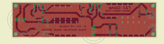
Anyway... it seems that separating "grounds" is the way to go... I came up to the conclusion that something like this -close to a star ground- should work out fine
The ground plane is divided into 3 areas:
- Input Ground
- Bias Ground
- Output ground
I have taken the occasion to improve some more with larger traces for high currents.
I'll have this etched after a few days... so comments / advices are still most welcome !
Attachments
Well as long as they tie back together at power supply I think it's okay.
On Peter Daniel's boards, the input G Speaker ground, DC grounds are tied together on that board. (I am pretty sure).
On Peter Daniel's boards, the input G Speaker ground, DC grounds are tied together on that board. (I am pretty sure).
Thanks Tea
As a matter of fact I also had "benchmarked" Peter's boards to see how he does it 😀 😀 😀
I am confident on the fact that the grounds all join together on the board (there is of course only ONE ground), but my questiom is more about in what "order" or what pattern I should connect them to prevent high currents to mix and interfere with signal...
Problem is, Peter uses a different layout than me so its hard to transpose exactly (and I was hoping to understand the theory behind proper PCB grounding🙄)
One part of the theory is that ground-return currents induce a voltage across the distributed impedance of each ground-return conductor. So at the non-power-supply end of each ground-return conductor (and proportionally all along the conductor) there will be a voltage that is not the same as at the power supply ground end of the conductor.
Larger ground-return currents will create larger voltage differences, with amplitudes proportional to the current's amplitude, across the resistive component of the ground conductor impedance (V = I x R).
Faster-changing time-varying currents will create larger voltage differences, with amplitudes proportional the current's time-rate-of-change, across the inductive component of the ground conductor impedance (v = L x di/dt).
If a single-ended amplificaion stage's input ground reference point shares a length of ground-return conductor with a significantly large and/or fast-changing ground-return current from another part of the circuit, then the "ground" voltage at that input ground reference point will be non-zero and/or time-varying, and that voltage will effectively be arithmetically summed with the input signal voltage!
But there's more.
You must also try to eliminate (i.e. minimize) "enclosed loop area", for all conductor loop pairs.
Look up Faraday's Law. A time-varying magnetic or electromagnetic field in the air will induce a corresponding time-varying current in any conductive loop. (And a time-varying current in any conductive loop will induce a time-varying electromagnetic field in the air.)
So, for example, signal input and its ground conductor should always be kept as close to each other as possible. But the same is true for ALL loops, which includes power (both AC and DC), signal, and outputs. Some of them mostly transmit and some mostly receive. It's best to minimize the loop areas of ALL of them.
Gootee,
we and many others must be posting in the wrong language.
This is being said so many times, I begin to wonder if any/many of our Members are capable of reading english !
we and many others must be posting in the wrong language.
This is being said so many times, I begin to wonder if any/many of our Members are capable of reading english !
Gootee,
we and many others must be posting in the wrong language.
This is being said so many times, I begin to wonder if any/many of our Members are capable of reading english !
I feel a fair bit of bitterness in your post.... (or am I wrong??)
maybe you could put yourself in the shoes of someone who does not know what Gootee just explained and do a research on DIYaudio , or even Google.
Now show me where I get this info synthesized , and explained half as clearly, and show me the links... I'd be very interested
And I did not ask anyone to explain the theory in the first place. For once Gootee did it clearly enough for a non electronics engineer to understand, and I thank him for that... but I believe my implementation is already more or less following these principles....
What I asked was if someone could tell me if my interpretation and implementation of good grounding was correct. Hence the PCB pictures
(I hope my capability of writing english is sufficient for you to understand what I need, and I hope the forum will still allow non native speakers in the future)
Besides, one of the issues most people face is, there are contradictory information on what should be done in terms of the implementation (ground planes, bus, stars, multiple stars, etc....).. the issue being what is good for audio frequency is not necessarily for HF, and each application is different,.... If it was so clear and easy, there would not be so many people with buzzing issues in their amp, and there would just be ONE way to ground described by a simple schematic.
I have not found that yet.
Please don't look at everyone who has not your level with a scorn, and let people like Gotee post their answers.... don't waste your time reading newbies / pupils / students / ... and reserve your valuable knowledge and help for people who most deserve it (please let us know the minimum university degree and curriculum to be allowed posting)
Last edited:
Gootee,
we and many others must be posting in the wrong language.
This is being said so many times, I begin to wonder if any/many of our Members are capable of reading english !
AndrewT,
I'll admit that once in a while I might think about it that way. But I think that the threaded discussion-group format does make it relatively difficult to find information (and especially the best information, or even not-incorrect information, about something), especially when one doesn't yet know what to ask, or, even if one does, what terminology might be used in the answers. So I can't usually blame other people, too terribly much, for not wanting to spend weeks or months rooting-out the knowledge they need. If I can help their learning curve go faster, it's probably good for the efficiency and progress of the universe, somehow, or at least good for them. Besides, I've gotten a lot of good practice at expressing the same ever-constant ideas and theories in many different ways, and I am getting the script to the point where it's fairly well polished, or at least easy to rattle off.
But what I think it really needs is to be illustrated with animated graphics that show the currents and voltages, and then maybe also with example photos or renderings of actual less-than-optimal layouts where hum or noise is induced (maybe with actual oscilloscope screen shots and photos of where the probes were, and even actual audio), followed by photos or renderings of corrected versions (and more scope shots). Maybe someday I'll tackle that. I wonder what kind of software people use for that type of animation. I guess GIF files would work, for animations to put on line. Just need a decent free GIF creator, I guess.
And I'm not what I would consider an expert at this stuff, anyway, and would welcome the opportunity, if I ever get the time, to try to find the answer(s) to the main question that I myself always have, and it's usually the same one, and that is, in general terms, "OK, there are these theoretical effects but how _significant_ are they, in most cases? And, for example, does one effect typically far outweigh the others? i.e. Is it worth the trouble of trying to mitigate the effect(s), or worth anyone's time to talk or even think about it?". Of course, with some audiophile-type pursuits, the questions and answers might have to be fine-tuned, so that the hardcore among us could know to go after the 0.01% stuff before they bothered with the 0.001% things. <grin>.
I'll have to try to remember to include RF considerations for audio circuits, too.
Cheers,
Tom Gootee
Last edited:
I feel a fair bit of bitterness in your post.... (or am I wrong??)
maybe you could put yourself in the shoes of someone who does not know what Gootee just explained and do a research on DIYaudio , or even Google.
Now show me where I get this info synthesized , and explained half as clearly, and show me the links... I'd be very interested
And I did not ask anyone to explain the theory in the first place. For once Gootee did it clearly enough for a non electronics engineer to understand, and I thank him for that... but I believe my implementation is already more or less following these principles....
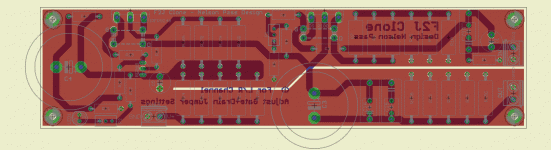
What I asked was if someone could tell me if my interpretation and implementation of good grounding was correct. Hence the PCB pictures
(I hope my capability of writing english is sufficient for you to understand what I need, and I hope the forum will still allow non native speakers in the future)
Besides, one of the issues most people face is, there are contradictory information on what should be done in terms of the implementation (ground planes, bus, stars, multiple stars, etc....).. the issue being what is good for audio frequency is not necessarily for HF, and each application is different,.... If it was so clear and easy, there would not be so many people with buzzing issues in their amp, and there would just be ONE way to ground described by a simple schematic.
I have not found that yet.
Please don't look at everyone who has not your level with a scorn, and let people like Gotee post their answers.... don't waste your time reading newbies / pupils / students / ... and reserve your valuable knowledge and help for people who most deserve it (please let us know the minimum university degree and curriculum to be allowed posting)
Lazybutt,
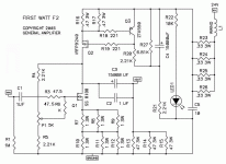
I had some ideas that might improve your layout but couldn't be sure without a schematic readily at hand and didn't want to say anything that was wrong. And I was too lazy to go looking for a schematic. If you post the schematic, or a link to it, I will take a look. The theories are nice but actual examples that are "close to home" can really help one to understand how to apply them.
I think that I understand how you arrived at your apparent perceptions and feelings, regarding AndrewT's post. But I believe that in this case you are mostly incorrect. I don't think he's bitter. Curmudgeonly and bluntly-spoken sometimes, maybe, but always dedicated to, and focused on, being helpful to (and concerned about the saftey of) the DIY community and communicating what people need to know. Maybe he was even simply irritated by seeing me post the same things, yet again, and over and over <grin>. (Actually, I imagine there was a bit of dry humor behind his post.) I must admit that even I sometimes get pretty tired of seeing him post, over and over like clockwork, about the proper way to do a safety-disconnect network, and about how dangerous the mains can be, and about using a light bulb tester for initial powering after any mod or build <smile>. (But then I think about what might have happened to certain people if he HADN'T. Oh my! I don't know how he can even stay sane knowing that he can't be everywhere at once. <grin!>)
I do know that over my years of reading this forum, I have noticed that AndrewT has very-generously been almost-exclusively extremely helpful to and caring toward many, many people, both the newbies and the experienced ones. So I would be inclined to make generous allowances for the occasional slip into impatience, or even bitterness, if it comes to that.
Enough said? Sorry to have blathered-on for so long about all of that.
Regards,
Tom
Last edited:
OK,
First of all, please apologize for the raving. and I should have posted the schematic in the first place... sorry about that.
I have not been around for a long time, and don't know yet how helpful AndrewT can be.
I think now that you have disambiguated the 2 main things to care about in grounding, I also have spotted some possible improvements,
I'll appreciate a lot your suggestions, although I'll also have to do my homework so don't spend too much time on it right now... the elephants in the china shop will already help (I'm not at home right now, so I'll do that at the end of the week),
Attachments
- Status
- Not open for further replies.
- Home
- Amplifiers
- Pass Labs
- F2J PCB: a question on ground layout