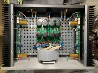
So far so good. The magic smoke that makes an amp sound good did not escape. Now biasing the amp and it is adjusting nice and easy. I’m letting it cook for a couple a little while and check bias. Next stop will be to see if it plays music.
Attachments

ah, reminds me of times of my youth, when I was able to see music ......... more time I was drunk than I wasn't, both from alcohol and hormones, but big help were light show lights and I especially likeds ancient ones with color oil filters ..........
these days, I insist on hearing music .........

these days, I insist on hearing music .........
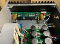
I connected the amp and have very little gain. Not sure what the problem is, but when I was doing my initial testing using my phone and some test speakers I had to max the volume to get sound. I put the amp in my system and it plays at low a low volume with the pre turned almost all the away. This is with a VTA SP14 that has a lot of gain. When I turn the volume up all the way the right channel distorts.
I set the bias on both channels to 12.93, because that was the max bias for the right channel.
Power supply under load is 24.17VDC.
Next step is to make sure all the parts are the right values and in the right spot. I built both boards at the same time, so it is not inconceivable that I made the same mistake on both boards.
Any help on what I should look for first would be appreciated.
Adjust pot to get a reading of one half of the DC-supply voltage just in front of the outputcap. Connect your DVM to GND and in front of the outputcap and adjust P1 to get the correct reading.
24.17VDC / 2 = 12.085VDC
Try that...
Do you have a way to measure gain? I use a signal generator and 'scope and measure Vin and Vout and do the math (by cheating with a web app) to calculate dB gain.
24.17VDC / 2 = 12.085VDC
Try that...
Do you have a way to measure gain? I use a signal generator and 'scope and measure Vin and Vout and do the math (by cheating with a web app) to calculate dB gain.
I thought that these amp were supposed to work the first time with no problems.
When I get a chance to get back into the amp. Probably this evening. I will make that adjustment. I will double check the voltage from the PS and half it on the output before the cap.
I do have a cheap DSO138, but have never used it and my knowledge is using a scope is limited. I guess it is a good time to learn. I do not have a signal generator. Maybe I can use an app on my phone.
I don't know the DSO138, so I looked it up. I see on the webpage that it has a "Built-in 1KHz/3.3V test signal". Could you run that through a pot or a voltage divider using parts bin resistors and get it down to .2 or .3V? Otherwise try the app on the phone. Measure actual voltage at input and output with scope.
I always have this website popped up on my phone when I'm doing this kind of thing. Go to "voltage and gain"
Decibels to Voltage Gain and Loss convert calculation conversion amplification amplifier electronics - sengpielaudio Sengpiel Berlin
You're looking for something around 14dB gain for F2J.
I always have this website popped up on my phone when I'm doing this kind of thing. Go to "voltage and gain"
Decibels to Voltage Gain and Loss convert calculation conversion amplification amplifier electronics - sengpielaudio Sengpiel Berlin
You're looking for something around 14dB gain for F2J.
The First Watt Products page shows the F2J to have 14dB of gain. That is 5X voltage gain.
For test signal, there are apps for phones and also downloadable wave files.
Use a meter and measure the AC Vrms of the amplifier input signal and of the amplifier output signal to check gain. Or use an oscilloscope.
Whoops, rthatcher answered while I was typing.
Also one thing to check is the Iq. Measure voltage across R16. R16 is paralleled with R17, so the combined resistance is 0.235R. Current should be about 2.7A, so voltage should be 0.235R x 2.7A = 0.63V.
Last edited:
rhthatcher,
Thank you for the link and the idea of using the test signal.
Ben Nah,
Using a meter sounds like the easiest to start with.
Thank you for the link and the idea of using the test signal.
Ben Nah,
Using a meter sounds like the easiest to start with.
I’m confused. Adjusted the bias to half the power supply. The power supply is 24.2vdc under load and bias is now 12.1vdc. Tested the AC voltage out of my phone using a test tone and it is .393v, but the voltage out of the amp is .080. It is the same in both channels.
The audio path is so short and voltages appear to be correct, so I’m at a lose. Any help on what to check is very welcome.
The audio path is so short and voltages appear to be correct, so I’m at a lose. Any help on what to check is very welcome.
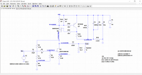
What value do you have in R6 (8.2K or 100K)? To confirm, have you skipped R2 and Z1 (protection nonsense parts)?
If so, find the end of R2 that connects to C1 and R3 and measure DC from there to GND. That's your gate voltage to the Semisouth - what is your gate voltage?
See if you can pick up any information from the DIY F2 clone thread - see MZM's post #611
DIY F2 clone
If so, find the end of R2 that connects to C1 and R3 and measure DC from there to GND. That's your gate voltage to the Semisouth - what is your gate voltage?
See if you can pick up any information from the DIY F2 clone thread - see MZM's post #611
DIY F2 clone
Last edited:
That is actually good. 0.615V/0.235R = 2.62A, which is close enough.
So far it looks good. Perhaps your R13, R14, and R15 are not 47R but 0.47R?
So far it looks good. Perhaps your R13, R14, and R15 are not 47R but 0.47R?
- Home
- Amplifiers
- Pass Labs
- F2J clone Build thread