Hi, I am considering to build the F5T V2 (50 watt) amp. Once built and biased, how to stress test the amp for a longer period (i.e. 2hr?) without connecting to speakers?
Thanks
Thanks
You could combine resistors in parallel to meet around 6ohms wattage rating should sum to over 50W. For example 3 x 18 ohm resistors rated at 20W in parallel will equal a 6ohm 60w resistor.
Stress? Just let it sit there. Idle is the most stressful for class-A

Can someone share high res inside photos of their F5T V3 (100 Watt mono block) showing the layout of the boards and power supply/transformer in the D5 chassis? Looking for ideas on how to mount the FE board.
RF Phil:
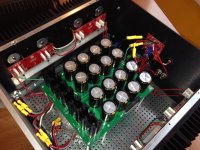
Here's one. A diyAudio soft start board is mounted to the interior surface of the front panel. For what little it's worth, I subsequently revised the power supply as a CRCRC, adding 90,000 uF as the third stage (for a total of 250,000 uF per channel), which nicely bolstered the low end. But the amps are otherwise unchanged from this photo.
Regards,
Scott
Attachments
Hi Scott:
Thanks for sharing.
Any challenges from EMI with having the PSU board over the toroidal transformer? Is the blue board on the rear panel the speaker turn-on delay/DC protector? Did you implement any slow start / soft start for the PSU?
Thanks,
Phil
Thanks for sharing.
Any challenges from EMI with having the PSU board over the toroidal transformer? Is the blue board on the rear panel the speaker turn-on delay/DC protector? Did you implement any slow start / soft start for the PSU?
Thanks,
Phil
Phil:
I've had no problems with the PSU directly over the toroid (in fact, I've done that on numerous builds without issue); I like the idea of having an open space in the chassis where rising air is not impeded by pcbs. Yes, the blue board located below the F5T front end pcb is a diyAudio speaker protection board. And yes, as mentioned in my post, a soft start is mounted on the inside surface of the front panel, just out of view in the photo.
Good luck with your build. I love my F5T V3s even though they are ridiculous overkill. I had a pair of Pass Labs Aleph 1.2 monoblocks for ages before building the V3s and it seems I got used to the look of a pair of hulking amplifiers between the speakers. If that is evidence of how shallow I am, so be it.
Regards,
Scott
starcat:
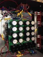
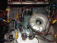
Here are a couple of photos showing the third power supply stage (i.e., an RC stage) with and without the CRC power supply board designed by and sourced from buzzforb, a (former?) diyAudio member who hosted an F5 Turbo components group buy about a decade ago. The capacitors are all Nichicon KG (15,000 uF on the baseplate and 10,000 uF on the ps pcb).
Regards,
Scott
Attachments
RFPhil, take a look at my post #1435 in F5 turbo illustrated build guide thread. I am using 47v rails with great success and am very happy, although for various reasons I’m thinking about converting to balanced. Another poster, can’t recall who, had great idea of using high standoffs and riser panels (diyaudiostore) to mount the fe board horizontally over the caps. My amps are dead quiet with fe board mounted on back panel above iec inlet. Best of luck with your build, you will love the end result
I've done something similar using riser panels to mount the PSU boards above the toroids in my dual mono F6.
F6 Illustrated Build Guide- DamonB dual mono F6
F6 Illustrated Build Guide- DamonB dual mono F6
I've been curious but never found an answer. I had considered dual mono PSes for my F6s but was unsure how close the rails would be for operating the amp as a balanced monoblock. What's the offset between the two positive speaker posts?
Hello everyone
I am looking at the F5T V2 build and would like to read papa's article . I found the schematic and BOM but need more info before I order parts and the 5U Deluxe. Can anyone share or refresh a link for that article? It seems that it has been removed from all sites.
Thanks all.
Mihail
I am looking at the F5T V2 build and would like to read papa's article . I found the schematic and BOM but need more info before I order parts and the 5U Deluxe. Can anyone share or refresh a link for that article? It seems that it has been removed from all sites.
Thanks all.
Mihail
Yes, thank you. I am finishing the Camp Amp monoblocks with the Nu tube Korg preamp. Got all parts and chassis for Aleph J, so I want to later to try a more difficult project once a get more experience. Its all fun to learn.
Mihail
Mihail
so I have updated parts. Q7 was c4793 Q8 was A1837 now I have tip32ag and tip31ag which spots do they go and Ty ahead of time
Google the datasheets and determine which is the N channel and which is the P.
Then look at the schematic symbols and insert in the proper positions.
Then look at the schematic symbols and insert in the proper positions.
Also, I got the amp up and running, keep in mind this is the cascode version. So I had to change resistors 7 years ago and I had a biasing problem then. The n channel would top out anytime I tried to go over 120mv. I could keep the channels in sync up to 120 mv. But to try to get to 380 the difference was p channel 380 n channel 280. I’m assuming a resistor needs to be changed. It sounded fine so I never messed with it. But I’ve updated with all new parts I would like to get it right.
And thank you 6L6
And thank you 6L6
Last edited:
- Home
- The diyAudio Store
- F-5 Turbo boards