See post 10 & 11 as a direct comparison between the 1.5" / 2.5" fins:
http://www.diyaudio.com/forums/pass-labs/184508-finished-f5.html#post2493407
The simulations were for 2 FETs each 32W, 12" extrusions, black anodised.
You are right in saying that reducing the length from 12" to 8" may not make much difference.
But I cannot tell you exactly how much, at least not this week.
And even though I have been quite successful in predicting heat sink temperatures, you should always do a test to verify.
Hope this helps,
Patrick
Patrick
YES! That's the post I saw, I couldnt remember where! I should have known it was one of your posts! It does look like your heat chart shows the piece to be a little on the edge. My understanding is 50 degrees is the most it should be. Thankyou for this input, I was looking everywhere for that post.
I do have Kerafol/Keratherm pads on the way, the chart seems to show the mosfet well over 50 degrees, I understand they make a difference, but I didnt know exactly how much.
Thanks for the post and reference to your findings.
Russellc
Last edited:
> My understanding is 50 degrees is the most it should be.
See:
http://www.diyaudio.com/forums/pass-labs/172770-balanced-f5-question-7.html#post2344426
Patrick
See:
http://www.diyaudio.com/forums/pass-labs/172770-balanced-f5-question-7.html#post2344426
Patrick
or like, +45 degr for the 'scared', 50 degr for the 'happy', +50 degr for more burning challenge, and the 'fearless'
which correlates to being able to keep you hand on the heatsink for longer, or very short, or not at all
and from what I understand the device casing will be like maybe 20-30 degr above that
ofcourse depending a lot on how effective your actual heat transfer really is
hell, even the individual NPN and PNP device might have slightly different heat transfer efficiency
related to mounting errors, heatsink surface issues, etc
differences might be severe , in a worst case situation
> +50°C for more burning challenge, and the 'fearless'
No, for those who believe in science and not gospel.
And of course, a DIYer does not sell a product.
Hence he would not get sued if the customer toasted his bobo while sitting on the heatsink to get a bit of extra warmth in cold winter days.
Patrick
No, for those who believe in science and not gospel.
And of course, a DIYer does not sell a product.
Hence he would not get sued if the customer toasted his bobo while sitting on the heatsink to get a bit of extra warmth in cold winter days.
Patrick
I think those were Nelson's figures, in a previous post, not long ago 😉
I just 'tweaked' the presentation a bit 😛
yeah, sure, knowledge is a good thing
what else would we do
and with mosfets and classA its 'the more the merrier'
which concerns both voltage and current
well, ofcourse we do have certain limits, sure
I think Nelson stated that the most estreme hot running F5 would be for the more experienced builder
Originally Posted by JamesBrennan4
Can the heat sinks for each device of one channel be separated - like on each side of the cabinet (for a F5 mono cabinet)?
I think you will find that output offset drifts quite badly if the tempco is inaccurate. A draught blowing on one side could be enough to send the output offset way too high. A lot of testing should be able to confirm if you can get the tempco close enough.
Good point. Maybe a F5 is too sensitive. Perhaps a Darlington emitter follower output stage with DC servo correction might be possible.
Thanks for your input,
Jim
Just stumbled on this, no nothing as to price or usability, but looking into it:
Extrusion Profiles
Only inch fins, maybe?
Russellc
Extrusion Profiles
Only inch fins, maybe?
Russellc
Not only does it have tall fins, but a wide pitch (11.5mm instead of the more common 10mm). So it will still be effective to a larger height than 150mm. A good sink for mini-tower type designs. But probably not cheap in small quantities.
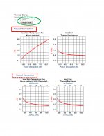
Aavid has good thermal curves which tells you exactly what increase in temperature at what power level at a specific extrusion length. You have to bear in mind that it still assumes uniform temperature at the back surface. So you should add say at least 5°C minimum for local temperature increase next to the MOSFETs.
Patrick
funny, their thermal curves ar shown for a fixed 6" length
and the thermal curves are based on varying airflow
and the thermal curves are based on varying airflow
I don't think you're going to beat Heatsink USA for value.
They are certainly the best deal that I have seen.
They are certainly the best deal that I have seen.
A while back someone complained that he was expensive and shipping was to much. I think he's very reasonable and the stuff is heavy to ship.
> funny, their thermal curves ar shown for a fixed 6" length and the thermal curves are based on varying airflow
My browser (Firefox) shows this (see below).
I have no problems changing the extrusion length and the unit at will inside the green box, and have noticed that the 4 graphs (both natural and forced convection) change accordingly to the new length.
Patrick
.
My browser (Firefox) shows this (see below).
I have no problems changing the extrusion length and the unit at will inside the green box, and have noticed that the 4 graphs (both natural and forced convection) change accordingly to the new length.
Patrick
.
Attachments
hey guys

i decided to give it a real world test . not just a simulation . using just ONE chunk of heatsinkusa 10.08" x 7" and mounting one channel , BOTH mosfets .

it's been up and running for almost 1 1/2 hrs . bias has stabilized at @.58-59v and it's nice and warm . temp readings pretty much everywhere on the heatsink are only 37-38 C . at the bolt and washer holding the fet they measure @62 c .
i'm using goop and the keystone micas .
cheers Woody
i decided to give it a real world test . not just a simulation . using just ONE chunk of heatsinkusa 10.08" x 7" and mounting one channel , BOTH mosfets .
it's been up and running for almost 1 1/2 hrs . bias has stabilized at @.58-59v and it's nice and warm . temp readings pretty much everywhere on the heatsink are only 37-38 C . at the bolt and washer holding the fet they measure @62 c .
i'm using goop and the keystone micas .
cheers Woody
I have no problems changing the extrusion length and the unit at will inside the green box, and have noticed that the 4 graphs (both natural and forced convection) change accordingly to the new length.
Patrick
ah, thats great

I didnt notice

clever 'tool', and practical
worth 'saving'
k , awesome corned beef (burp) , it's been running close to 4 hours and after it stabilized i biased it at .60v . rails are @23v
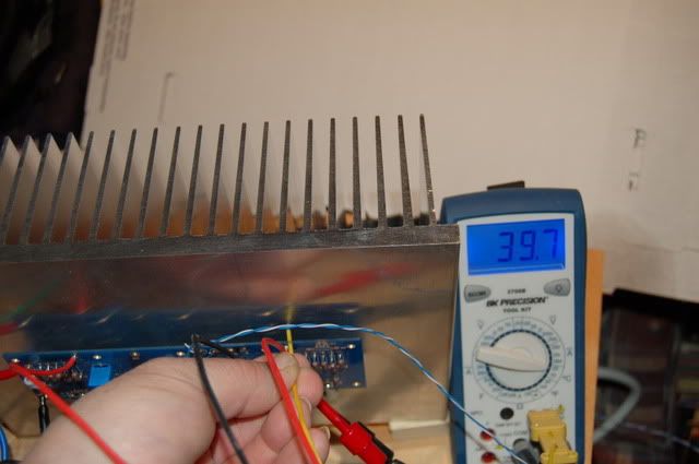
that's degrees C on the meter taken @ 2" over the fet . i could leave my hand on it all day .
the mosfets are mounted with silicon heatsink compound and keystone micas .
the input is shorted .
am i missing something ? hey i'm new at this and learning , any input appreciated .
cheers Woody
that's degrees C on the meter taken @ 2" over the fet . i could leave my hand on it all day .
the mosfets are mounted with silicon heatsink compound and keystone micas .
the input is shorted .
am i missing something ? hey i'm new at this and learning , any input appreciated .
cheers Woody
hey guys
i decided to give it a real world test . not just a simulation . using just ONE chunk of heatsinkusa 10.08" x 7" and mounting one channel , BOTH mosfets .
it's been up and running for almost 1 1/2 hrs . bias has stabilized at @.58-59v and it's nice and warm . temp readings pretty much everywhere on the heatsink are only 37-38 C . at the bolt and washer holding the fet they measure @62 c .
i'm using goop and the keystone micas .
cheers Woody
If the fet is at 62, its too hot. I thought 50 for the mosfet was the limit?(or thereabouts), point is 62 sounds too high, no? Well, if the Mosfet is at 62 anyway...
Russellc
50 C is for the heatsink as far as i know according to NP :
"Again, the heat sinks on this amplifier run fairly hot, and you want to make sure
that they get adequate ventilation. They will run at around 25 degrees C.
above the ambient temperature, which puts them around 50 degrees in the
average listening room. At this temperature you should be able to put your
hand on them for about 5 to 10 seconds or so."
also "Heat Sinking
At 1.3 amps per channel, you will see idle heat dissipation of 62 watts. To keep the
temperature rise of the heat sink to 20 deg C." NP
temps mentioned are heatsink temps , not at the mosfet . my mosfets are mounted using NP's methods as far as i can deduct .
so far everyone here seems to claim this or that . at one point i said that it would be nice if folks could post ACTUAL temp readings for their specific setups and was immediately shot down by a mod here saying they were irrelevant .
these ARE actual temp readings for a heatsinkusa chunk of their 10.08" x 7" heatsink biased at .60v using an antec 5218 , cvillar/diyaudio boards .
cheers Woody
50 C is for the heatsink as far as i know according to NP :
"Again, the heat sinks on this amplifier run fairly hot, and you want to make sure
that they get adequate ventilation. They will run at around 25 degrees C.
above the ambient temperature, which puts them around 50 degrees in the
average listening room. At this temperature you should be able to put your
hand on them for about 5 to 10 seconds or so."
also "Heat Sinking
At 1.3 amps per channel, you will see idle heat dissipation of 62 watts. To keep the
temperature rise of the heat sink to 20 deg C." NP
temps mentioned are heatsink temps , not at the mosfet . my mosfets are mounted using NP's methods as far as i can deduct .
so far everyone here seems to claim this or that . at one point i said that it would be nice if folks could post ACTUAL temp readings for their specific setups and was immediately shot down by a mod here saying they were irrelevant .
these ARE actual temp readings for a heatsinkusa chunk of their 10.08" x 7" heatsink biased at .60v using an antec 5218 , cvillar/diyaudio boards .
cheers Woody
I havent re read yet, if its 50C for the heatsink, then that's great. I have a batch of Kerafol on the way, they are supposed to help a little in this regard. I would love to use this sink. What a bargain it is!
Russellc

- Status
- Not open for further replies.
- Home
- Amplifiers
- Pass Labs
- F-5 heatsink query