So I'm developing a modified JCM800 EF80 micro amp that has a CF cathode at 190Vdc hence elevating the heaters for all tubes to +75Vdc. Rather than have HT switch straight on with solid state, I have the option of using EZ81s which would provide a nice option rather than having a HT switch. As this is more todo with amps in general, I hope you don't mine the question here.
The question is - can you use the EZ81 with elevated heater supplies?
I have a two independent supplies (hence two EZ81s) referenced to ground, the Power state HT supply provides the elevation reference. Thus it's possible for the EZ81 would need to cope with both scenarios:
A) EZ81 sees 0V HT and +75V heater
B) EZ81 sees Full HT and +75V heater
The EZ81 datasheets seems to indicate Vfk as 500V (JJ) but as k positive and f negative (Phillips). So this seems to suggest scenario A would cause a problem.

I'm afraid that "elevating the heaters for all tubes to +75Vdc" means "all tubes"== all amplifying tubes AND rectifier.
Not a good omen to connect rectifier heater (even if it indirect heating) to another tubes heater.
Not a good omen to connect rectifier heater (even if it indirect heating) to another tubes heater.
The EZ81 datasheets seems to indicate Vfk as 500V (JJ) but as k positive and f negative (Phillips). So this seems to suggest scenario A would cause a problem.
There usually is a difference between the voltage valves can handle with heater positive or heater negative with respect to the cathode, and heater positive is the worst case, but your 75 V is so far below the 500 V rating that I wouldn't worry about it.
See K. Rodenhuis, H. Santing and H. J. M. van Tol, "The life and reliability of valves", Philips Technical Review vol. 18 (1956/1957), no. 7, 15th December 1956, pages 181...216 if you want to know the physics behind it. It is a very readable article and it can be found on the Internet somewhere. Pages 188 and 189 are the most relevant ones.
But that is the historic application for EZ81, to be run from a single heater winding for all valves in a radio or amp. So the omens are ok.I'm afraid that "elevating the heaters for all tubes to +75Vdc" means "all tubes"== all amplifying tubes AND rectifier.
Not a good omen to connect rectifier heater (even if it indirect heating) to another tubes heater.
The concern perhaps is more about whether this situation can be made bullet-proof for EZ81 that are decades old and the small % that could cause a cathode to heater low resistance or short. If the heater was solidly grounded, via a heater winding CT, then a short would short the HT winding to ground which could be 'protected' by a HT winding CT fuse (as well as protecting against other B+ related accidents).
If the heater has a humdinger to ground, then the fault current may be suppressed and a fuse may take longer to operate. If the heater was dc voltage elevated, then its unlikely that a fuse would operate, due to the resistance to ground used by the elevation network, and other collateral damage to circuitry could follow.
The KISS principal would initially ask whether the elevation is really needed - eg. is your B+ getting close to the 500V h-k limit of the EZ81, or are you doing it for stress on the cathode follower valve, or ... ?
It's specifically for stress on the cathode follower - a 12ax7 that sits on the JCM design at B+ (350V) on the plate with the cathode at +196V with a directly connected grid to the previous stage. This time honoured design is known to be harsh on V3 which houses the previous preamp 3 and the cathode follower.

The 12ax7 itself has a limit for heater to cathode of ±200V which means the cathode at 196V is very close. Probably OK for old 12ax7 but new construction 12ax7 I would be concerned about. Elevating the 12ax7 heaters by 75V is within spec to all the heaters and reduces the possibility of an arc over in V3's cathode follower.
I agree - bulletproof is good. This is why I'm considering the EZ81 as I don't want the HT going to the front panel "standby" switch which would be rated at 250V, even if Fender/Marshall has being doing that since the amps were first produced!
I need to look at the what impact a crowbar could cause there's numerous aspects on this due to capacitors simply shorting through that etc.
To answer the question on why two power supplies, the EF80 has a plate limit of 300V compared to the EL34/6550 that normally sits in that position. I can't then have that higher current flow EF80 B+ tap at the start of the B+ line. I could add a resistor in series with the output transformer CT but it would dissipate approximately 3W heat under the chassis (although it would add noise it's on the push pull B+ so the majority would cancel, the general heat would add thermal noise generally to what is a high gain amp).
Therefore I decided to put the three 12ax7s on a pre-amp PSU and the LTP and output tubes on a separate power-amp PSU. This is also a tinkering amp.. so I'm expecting to add and effects loop Buffer and a tube reverb section in the preamp and possibly experiment with different tubes (not blindly tube rolling but designing, for example, a triode output section). However starting with the basic build is first but if you're wondering why separate PSUs it enables future flexibility in this case.
Last edited:
Ok, so following the risk scenario that the EZ81 cathode has a significant leak, or even short, to heater, then all the heaters get raised to that EZ81's B+ level, as the divider used to provide heater elevation is unlikely to restrain the heater dc voltage above a certain level of heater-cathode leakage.
You could mitigate that risk by periodic maintenance, ie. measure the heater-cathode insulation resistance at say 500Vdc of appropriate polarity, and hope there is no rapid insulation demise between measurements.
Another path could be to add a beefy zener to the elevated heater, such that the zener doesn't conduct unless the heater dc voltage to 0V exceeds a certain elevation. Not all zeners are a low power single part that would fail open rapidly - ie. you can make a beefy zener with say a FET and TL431.
Another path is to do nothing, and play the odds. If a short does occur then fix all the collateral damage.
The EF80, a 2.5W VHF Pentode with a 650k Ohm plate resistance @ 250V, difficult to match an output transformer.
Why not use Rob's 6V6 schematic and a power soaker (attenuator) if to loud. It'll be less trouble.
https://guitar.com/guides/diy-workshop/diy-workshop-build-your-own-attenuator/
Why not use Rob's 6V6 schematic and a power soaker (attenuator) if to loud. It'll be less trouble.
https://guitar.com/guides/diy-workshop/diy-workshop-build-your-own-attenuator/
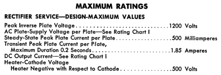
The JJ data sheet for the EZ81 gives the limiting value as Ukf not Vfk. Ukf means potential of cathode with respect to filament. Also, if you look at the GE 6CA4 data sheet, it says specifically "Heater negative with respect to cathode".The EZ81 datasheets seems to indicate Vfk as 500V (JJ) but as k positive and f negative (Phillips). So this seems to suggest scenario A would cause a problem.
There is no problem with elevating your 6.3v filament circuit to 75 volts.
Attachments
- Home
- Amplifiers
- Tubes / Valves
- EZ81 on an 75V elevated heater supply?