I am looking to put a pair of 1629 magic eye tubes in a preamp as crude level meters. I don't need to them to be accurate, only to pulse with the music.
The data sheet for the 1629 is here http://www.mif.pg.gda.pl/homepages/frank/sheets/049/1/1629.pdf and a description of how to hook it up is here http://www.mif.pg.gda.pl/homepages/frank/short/039/1/1629.gif
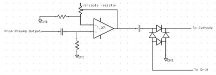
Essentially, the idea, as I understand it, is to put 250V on the plate, the cathode to ground, and vary the grid from 0 to -8V. This circuit I drew up is supposed to give the grid the 0 to -8V. Essentially, it takes the signal form the preamp output, runs it through an opamp with a variable resistor to control gain so one can increase the output when the volume is low and decrease it when it is high so that all listening levels can use the full range of the eyetube. This signal is then rectified and sent to the tube.
Will this work as a concept, and/or are there any changes I should make? The tube needs 12.6V for the heater, so I thought I'd also use +/-6.3V for the opamp.
The opamp portion is just a cmoy, btw.
Thanks,
-d
The data sheet for the 1629 is here http://www.mif.pg.gda.pl/homepages/frank/sheets/049/1/1629.pdf and a description of how to hook it up is here http://www.mif.pg.gda.pl/homepages/frank/short/039/1/1629.gif
Essentially, the idea, as I understand it, is to put 250V on the plate, the cathode to ground, and vary the grid from 0 to -8V. This circuit I drew up is supposed to give the grid the 0 to -8V. Essentially, it takes the signal form the preamp output, runs it through an opamp with a variable resistor to control gain so one can increase the output when the volume is low and decrease it when it is high so that all listening levels can use the full range of the eyetube. This signal is then rectified and sent to the tube.
Will this work as a concept, and/or are there any changes I should make? The tube needs 12.6V for the heater, so I thought I'd also use +/-6.3V for the opamp.
The opamp portion is just a cmoy, btw.
Thanks,
-d
Attachments
If you want to see some action, and not a simple "volume" indicator, use half wave rectification.
my 0,02€ 🙂
my 0,02€ 🙂
Simpleton said:If you want to see some action, and not a simple "volume" indicator, use half wave rectification.
Really? Why?
Asside from the type of rectification to use, any other thoughts on the concept?
Why not get serious about this? As in the following peak reading magic eye VU meter: http://koti.mbnet.fi/siliconf/JukkaTolonen/ga/peakmtr/peakmtr.html
OK, maybe not A volume indicator , but there is no need to read the (in this case, as we want negative grid bias) positive half cycle of the signal, as only the peak function is needed. You should consider getting a resistor connecting the grid cap to ground (the peak hold function).
One other thing ( and i may be wrong, as with the above), depending on the magic eye tube, and vaguely remembering the vaguely learnt theory of opamps, you might get only the signal to pass to -6.3V.
The link heater posted is very good. 😉
One other thing ( and i may be wrong, as with the above), depending on the magic eye tube, and vaguely remembering the vaguely learnt theory of opamps, you might get only the signal to pass to -6.3V.
The link heater posted is very good. 😉
What is that funny triangle-shape tube?
Your 4-D rectifier is dubious. It is full-wave (pointless for "to pulse with the music") but has has no peak-hold (nice for speech/music). It looks like when the cathode is driven, the grid floats, and vice versa?
The simplest way is to drop B+ to 100V and put audio direct on the grid. This will jiggle fine, at either CD-deck output or power-amp input levels. At 100V supply the eye closes around 2.5V.
You can, of course, if you must, put that triangle-tube (chip???) in front for variable gain.
Peak-hold is nice, but needs a rectifier. A proper full-wave rect is complex and will look the same for "pulse with the music" uses. While speech/music can be asymmetrical, it usually isn't too asymmetrical, and you are not asking for any precision, only jiggle.
Use your booster driving one diode onto a cap/resistor combination to ground. Say 0.01uFd and 1Meg. The eye-tube grid connects to the top of the R||C. Diode is polarized for negative output. A few-K in series with the diode will keep it from holding very-short transients and give more jiggle.
For less jiggle but no gain-knob, do a rude log conversion on the input. Opamp with diode feedback. Yeah it has crummy tempco, but you don't care.
An externally hosted image should be here but it was not working when we last tested it.
1629 Cats Eye
dsavitsk,
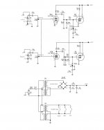
How about his one. Is a design by MapleTree Audio that they had posted on their website for years. I would have just forwarded the link but, could no longer find the lin to the assembly manual. Should be realatively easy to build
Cheers -ALBQ
dsavitsk,
How about his one. Is a design by MapleTree Audio that they had posted on their website for years. I would have just forwarded the link but, could no longer find the lin to the assembly manual. Should be realatively easy to build
Cheers -ALBQ
Attachments
hey!
I have a nice one for you .... ALL TUBE
you can adapt it to use virtually all indicators that need a - voltage at the grid.......
http://www.aha.nl/tubelevel.aspx
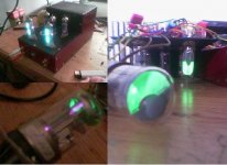
here a picture of the vu-meter with
-EM84
-EM85
-EM71 (test)
I have a nice one for you .... ALL TUBE
you can adapt it to use virtually all indicators that need a - voltage at the grid.......
http://www.aha.nl/tubelevel.aspx
here a picture of the vu-meter with
-EM84
-EM85
-EM71 (test)
Attachments
I remember this one! 😀
I was published in glass-audio or something, wasn't it?
I thought the website (your?) was down...
I was published in glass-audio or something, wasn't it?
I thought the website (your?) was down...
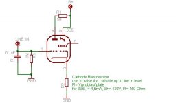
I've connected my 6E5 for trying out my schematic, using a portable cd player as the source.
It works pretty well, the cathode resistor can be droped of the circuit with no problems. As expected, phones-out gives a bigger angle variation comparing to line-out, especially with bass enhancement on.
The new version, based on my tries, is attached.
Have fun, that's what tubes/valves are all about!
Attachments
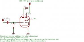
Nitpicking:
Your diagram shows the 'D' electrode (no. 7 in your drawing) as
unconnected. This is always internally connected to the triode
anode (no. 9). Or else there will be no light show...😀
Morgan
Your diagram shows the 'D' electrode (no. 7 in your drawing) as
unconnected. This is always internally connected to the triode
anode (no. 9). Or else there will be no light show...😀
Morgan
(looking for baseball bat)
Morgan, i tell in the schematic i picked up a "general" (em87, or something) magic eye, what matters is the idea per se. If i was doing the schemkatci for every magic eye, i would be here until tomorrow! 😀
take care!
Morgan, i tell in the schematic i picked up a "general" (em87, or something) magic eye, what matters is the idea per se. If i was doing the schemkatci for every magic eye, i would be here until tomorrow! 😀
take care!
@simpleton....
I don't know if it was in glass-audio....found it a long time ago when surfing the net...
sure my next amp will have it built in!
I don't know if it was in glass-audio....found it a long time ago when surfing the net...
sure my next amp will have it built in!
To add to this list, here is the eye tube circuit from the Cary 805c. http://www.ainamoi.com/images/cary 805c/page16.jpg It appears to run from the speaker outputs rather than fom line level -- any suggestions on what t change to adapt it to line level input voltages?
-d
-d
- Status
- Not open for further replies.
- Home
- Amplifiers
- Tubes / Valves
- Eye Tube (1629) controller help