Hi folks.
I need some help/pointers in designing an external power supply for a Quad 22 control unit.
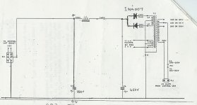
After much searching I came across the diagram which I've posted. Not sure of the value of the choke but I presume it is the same as the one in the Quad II, as this is where the drawing appears to have been culled from.
I have several EZ80s lying around - would it be better to use these to keep the tradition of using a valve regulated PSU instead of diodes?
Whilst I've rebuilt my Quad IIs several times, and have recently completed a Dynaco ST70 kit and VTA driver board, I really don't have much of a clue in designing power supplies, so any help would be grately appreciated. In particular are there any suitable transformers I could pick up from somewhere like Maplins or RS which wouldn't break the bank? The PSU requirement of the Quad 22 is 330V 4.5mA.
The Quad IIs will be using independent mains leads now BTW, and no longer powered by the Quad 22.
Thank you,
- John
I need some help/pointers in designing an external power supply for a Quad 22 control unit.
After much searching I came across the diagram which I've posted. Not sure of the value of the choke but I presume it is the same as the one in the Quad II, as this is where the drawing appears to have been culled from.
I have several EZ80s lying around - would it be better to use these to keep the tradition of using a valve regulated PSU instead of diodes?
Whilst I've rebuilt my Quad IIs several times, and have recently completed a Dynaco ST70 kit and VTA driver board, I really don't have much of a clue in designing power supplies, so any help would be grately appreciated. In particular are there any suitable transformers I could pick up from somewhere like Maplins or RS which wouldn't break the bank? The PSU requirement of the Quad 22 is 330V 4.5mA.
The Quad IIs will be using independent mains leads now BTW, and no longer powered by the Quad 22.
Thank you,
- John
Attachments
John,
It might be worth your while to order from this side of the salty "pond".
The prices AnTek charges are attractive and the exchange rate is still in your favor. AnTek's model AN-1T150 looks like it could be adapted to your needs.
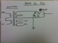
Wire the 2 secondaries in series and hybrid bridge rectify using snubbed UF4007s on the ground side and an EZ80/6V4 on the B+ side. Use 1 of the 2X 6.3 VAC windings for the rectifier and the other for the signal tubes.
Obviously, you will wire the dual primaries in series. 4 lbs. is approx. 1818 grams.
It might be worth your while to order from this side of the salty "pond".
The prices AnTek charges are attractive and the exchange rate is still in your favor. AnTek's model AN-1T150 looks like it could be adapted to your needs.
Wire the 2 secondaries in series and hybrid bridge rectify using snubbed UF4007s on the ground side and an EZ80/6V4 on the B+ side. Use 1 of the 2X 6.3 VAC windings for the rectifier and the other for the signal tubes.
Obviously, you will wire the dual primaries in series. 4 lbs. is approx. 1818 grams.
Thanks for that Eli that looks great 🙂
I'll draw up a diagram before I do any wiring to make sure I've got it right and post it here.
Thanks again mate,
- John
I'll draw up a diagram before I do any wiring to make sure I've got it right and post it here.
Thanks again mate,
- John
Hi Eli.
Would it be possible for you to post a diagram of the circuit you describe above please? Want to make sure I understand the circuit before I blow meself up 😉
Mucho thanks,
- John
Would it be possible for you to post a diagram of the circuit you describe above please? Want to make sure I understand the circuit before I blow meself up 😉
Mucho thanks,
- John
 )
)
Hi John,
Yes that is just fine as drawn.. Observe the maximum rated input capacitance for the 6V4 and you are all set.
Yes that is just fine as drawn.. Observe the maximum rated input capacitance for the 6V4 and you are all set.
Why not try your hand at a regulated PSU for the tube pre-amp? It will make the worlds difference in sound quality and will be much more compact than a CLC style PSU.
Cheers Kevin - I'll do that.
DeltaVector: Well 1) I already have all the parts for this PSU, and 2) I'm a beginner really when it comes to valve amps and PSUs. Perhaps when I have this one up and running I'll look into upgrading it - thanks for the suggestion 🙂
DeltaVector: Well 1) I already have all the parts for this PSU, and 2) I'm a beginner really when it comes to valve amps and PSUs. Perhaps when I have this one up and running I'll look into upgrading it - thanks for the suggestion 🙂
johnm said:Cheers Kevin - I'll do that.
DeltaVector: Well 1) I already have all the parts for this PSU, and 2) I'm a beginner really when it comes to valve amps and PSUs. Perhaps when I have this one up and running I'll look into upgrading it - thanks for the suggestion 🙂
John, when you're ready to experiment with regulated supplies, I have some very rugged, simple, and good performing tube designs you can try. Just shoot me an email.
Just want to make sure I have this down right.
The transformer secondaries on the torroidal I have are 2 x red/yellow (2 x 0-150V).
Often I have seen the two center sections connected together, and this is the 0V or CT, correct?
BUT in this case (diagram a few posts above) the CT is not connected to ground, so I get 0V and 300V?
As an aside, anyone got any good links to transformer basics? I tried Googling and - surprisingly - didn't find anything that answered my above questions.
Lastly, am I OK going with 32uF for the smoothing cap?
Cheers,
- John
Should my CT goto ground in this circuit,or do I attach the two CT wires together and insulate?
Thank you.
Thank you.
John,
You are wiring things in series, on both sides of the AN1T150. Connect a red wire to a black wire and insulate well. The "free" red and black wires connect to the AC mains. Connect a yellow wire to a white wire and insulate well. The "free" yellow and white wires connect to the hybrid bridge rectifier. The rectifier winding of the power trafo has no direct connection to ground.
Use UF4007 diodes in parallel with 10 nF. snubber caps. on the SS side of the rectifier bridge. Either NPO ceramic or MPP parts rated for not less than 1200 WVDC make suitable snubbers.
32 μF. at the I/P of the PSU filter is fine. The EZ80/6V4 can tolerate working into as much as 50 μF.
Many thanks Eli that's great 🙂
Do I need/is it wise to put in a couple of voltage limiting reistors before the rectifier? I've noticed this done in some circuits, others seem to leave them out altogether. Guess I'd need to see what my real world voltages are and then decide?
Lastly, I'll go with the 32uF Polypropylene filter cap since you say the max the EZ80 can handle is 50uF. If you look at the Quad 22 circuit there are also two 16uF caps - C12 and C15. Would I need to get rid of any of these as I am using a 32uF?
Alternatively do I leave out the 32uF and just build as-is?
Quad 22 circuit is: http://www.geocities.com/ResearchTriangle/Lab/6722/quad22cir.html
Note: C7 - also 16uF - is not used in my design as I've cut out the EF86 stage and just using line level sources.
Many thanks,
- John
- Status
- Not open for further replies.
- Home
- Amplifiers
- Tubes / Valves
- External PSU for Quad 22 pre-amplifier