hey forum, its been a while since ive been around but im working on a new kicker cab for my rig.
ive come up with a design that certainly fits the design brief, that is "to kick like an angry mule"
but im just not sure on what ive drawn matching the numbers.
hopefully this works>
edit:
to add to this as a central kick bin to create a harder hitting midbass as im in process of building two more subs.
ive come up with a design that certainly fits the design brief, that is "to kick like an angry mule"
but im just not sure on what ive drawn matching the numbers.
hopefully this works>
An externally hosted image should be here but it was not working when we last tested it.
edit:
to add to this as a central kick bin to create a harder hitting midbass as im in process of building two more subs.
An externally hosted image should be here but it was not working when we last tested it.
i wanted something like a USB or a HD215 but according to Hornresp the drivers sim terribly in them.
im chasing 90hz up to 250 or as high as they will feasibly go while still sounding ok.
i had a front loaded design thats pretty much flat from 90 to 500hz (bit wavy but +/-5db)
just gonna be a pain to design the cabinet. i dont trust myself to get it good.
im chasing 90hz up to 250 or as high as they will feasibly go while still sounding ok.
i had a front loaded design thats pretty much flat from 90 to 500hz (bit wavy but +/-5db)
just gonna be a pain to design the cabinet. i dont trust myself to get it good.
98 500 17.10
500 500 10
500 3080 60
3080 4034 25
VRC 12 VTC 2700
LRC 10 ATC 930
those are the HR numbers for the other cab if anyone wants to have a crack at a design for me ??
500 500 10
500 3080 60
3080 4034 25
VRC 12 VTC 2700
LRC 10 ATC 930
those are the HR numbers for the other cab if anyone wants to have a crack at a design for me ??
Klampy you can get more kick if you cluster the subs and study up on arraying, having bass cabs separated by an appreciable distance is going to cause cancellations looking at your picture i'd guesstimate that those stacks are 16 feet apart you could be losing spl anywhere between 70Hz and 120 depending on where your standing in the soundfield.
oops just noticed the cleverly disguised subs doubling as a DJ table the notch might be more like 140 territory.
oops just noticed the cleverly disguised subs doubling as a DJ table the notch might be more like 140 territory.
Don't so much focus on the image it was just for reference. I plan on running the subs in a full row with kicker in the center and horns up on tripods nice n high.
Morseo want to ensure my hornresp numbers and drawn plan is correct
Morseo want to ensure my hornresp numbers and drawn plan is correct
Yeh me too. I've been successfully using it to sim car subs but the horn path just doesn't look right but response wise it's what I want.
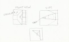
i wish i had a better view of the thumbnail of your drawing. i can't visualize where the "stub" is located?
converting the Hornresp schematic into a blueprint isn't easy sometimes without CAD software.
converting the Hornresp schematic into a blueprint isn't easy sometimes without CAD software.
Last edited:
If you can see my picture at all, the driver is on the right, facing into the triangular throat with the magnet in the mouth, it folds around the back to the left and then on the left wall is the mouth opening up against the back of the driver.
It just looks odd to me but if it's right and it'll get me the response I'm chasing then it'll make me happy coz I've got a spare 2x4 sound processor and a spare pair of amp channels 🙂
It just looks odd to me but if it's right and it'll get me the response I'm chasing then it'll make me happy coz I've got a spare 2x4 sound processor and a spare pair of amp channels 🙂
but the stub length doesn't seem to be there? if you make a paper template of the schematic and fold it in half so the speaker locations line up you might get the sense of what i see as a problem.
the expansion "shoulders" at the beginning of the mouth area also don't appear to be implemented in the drawing?
the expansion "shoulders" at the beginning of the mouth area also don't appear to be implemented in the drawing?
I've drawn it and now I can't post it off my tablet...
The rear port type area expands at almost the same rate as the shoulder section on hr which is why I didn't add an extra expansion at the mouth .
It seemed close but yeh just not quite sure
The rear port type area expands at almost the same rate as the shoulder section on hr which is why I didn't add an extra expansion at the mouth .
It seemed close but yeh just not quite sure
I'd prefer to build the front loaded horn coz it Sims flat from 90 to 400hz but it's very precise with it's measurements. A few mm either way and it gets very dippy in the response
So it needs to be a straight horn but it's over a metre long hornpath. I'm not sure a box over a metre deep is appropriate for my purpose
However it'd be perfect as a single cab for bridging the gap of sub to upper mid
Hmm perhaps I should just do it .
So it needs to be a straight horn but it's over a metre long hornpath. I'm not sure a box over a metre deep is appropriate for my purpose
However it'd be perfect as a single cab for bridging the gap of sub to upper mid
Hmm perhaps I should just do it .
hmm apparently i cant edit posts after 30 mins... interesting.
An externally hosted image should be here but it was not working when we last tested it.
I think I might just end up building it as a front loader and just accept that it'll be fairly large(long)
I wanted this cab to replace my current mt130 but as a tapped horn it'll only fill a tiny gap in response between sub and mid.
The way you've drawn it makes sense but is way more detailed in construction than I had intended.
I'll build a basic unfolded horn and use that as my kick bins.
I may actually be able to draw it up and have a pair built before new years yet.
Got two more SS15 to build too yet.
Edit:
Unfolded should get me the upper frequency needed to meet my upper mid horns too.
If these kickers go to plan there will be much drinking being had for sure haha
I'll put up a HR plot tomorrow of the FLH. It's super flat. And loud.
I'll put up a HR plot tomorrow of the FLH. It's super flat. And loud.
- Status
- Not open for further replies.
- Home
- Live Sound
- PA Systems
- External opinions requested please