Hi All. Continuing the saga of the preamp dual op-amp passive phono amp I'm mucking about with. The small built in dual rail power supply, it seems, is creating some hum especially with the channel it is nearest too. I would like to use a wall adapter ac/ac plug in transformer to power it but realise the design using a bridge rectifier on board needs a centre tap on the twin AC feeds so I would need to make up my own transformer box and run a 3x wire supply to the preamp (maybe a 4x wire if earth included). HOWEVER I note most commercial phono amps such as the REGAs or DJpreii use just a single phase, 2x wire AC supply. I can only assume they use some extra trickery in their power supply or they might even be single ended. How can I emulate their power supply design please? This way, I can use a simple power supply socket on the pre-amp rather than rig up a bulkier multi-way socket.
This is how Rega does it with one of their designs....seems like single-ended though and not useable for me....maybe all the others are too?
Attachments
Last edited:

Thanks very much Mooly. I wonder if the half wave rectification causes more ripple... I suppose it does but the regulators take care of that presumably? Could 2x bridge rectifiers then be used instead of the 2x diodes?
The ripple is at an effectively lower frequency 50 or 60 Hz for the half wave setup here rather than 100 or 120 Hz for a full wave bridge which means larger caps are needed to bring it down to the same level but for a small low power circuit it is a non issue. A phono preamp draws milliamps and yes, the regulators will give a totally clean supply.
Thanks again Mooly. Yes bigger caps needed to provide the same ripple input as the full wave set up. Cheap enough though. You might have missed my late added question: Could 2x bridge rectifiers be used for their smoother rectification? I have had a quick draw up but it looks like it results in a dead short through both of them where you join them at the zero/centre rail?...Not sure though?
Could 2x bridge rectifiers be used for their smoother rectification? I have had a quick draw up but it looks like it results in a dead short through both of them where you join them at the zero/centre rail?...Not sure though?
You've sussed it out 🙂 You can't have the advantages both. The half wave setup is fine for low current applications though.
As regards choosing half wave rectifier diodes, would Schottky diodes be preferred. The lower forward voltage drop would mean they would conduct a little earlier thus making the pulse gap spacing very slightly (very slightly) narrower on the sine wave input to them?
Interesting question. If you close the 'pulse gap' up as you say then that would mean the frequency of the ripple was higher and that can not happen... however 🙂
Lets try it in the simulation and see what happens. I've tried a few Schottky's and they all basically behave the same. The lower forward volt drop as expected gives better efficiency and a slightly higher DC across the reservoir cap.
The circuit on the left was just copied over and duplicated with a Schottky for the positive rail rectifier in the one on the right.
The bright green trace is the standard diode, the other the Schottky. You can see the higher DC produced. For this simulation I reduced the load resistor to make it all look more dramatic and increase the ripple.
The second image adds the incoming positive cycle so can see the different points the two diodes begin to conduct at.
So up to you 🙂
What's the purpose of D1 and D5?Found it, I knew I had this somewhere. This shows the kind of thing to expect.
View attachment 1055955
I'd put antiparallel diodes across the regulator outputs, preferably Schottky's although 1N40xx's usually also do the trick. The idea is to ensure that the op-amp circuit can't pull the positive output negative or the negative output positive at start-up, so nothing will go into (destructive) latch-up.
What's the purpose of D1 and D5?
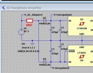
Deriving a low current dual rail supply from a single AC winding is easy.
This shows the ever popular 02 headphone amp supply.
You need to see the whole circuit 🙂 The circuit (apart from different regs) is from the 02 headphone amp. Battery/mains...

I'd put antiparallel diodes across the regulator outputs, preferably Schottky's although 1N40xx's usually also do the trick. The idea is to ensure that the op-amp circuit can't pull the positive output negative or the negative output positive at start-up, so nothing will go into (destructive) latch-up.
Good point.
If the op does go down this route then the anti parallel diodes is a good idea. Latch up of regs is a real problem... one of those weird things... but it is real in some configurations.
I think I used the word antiparallel incorrectly. I meant diodes in reverse from each output to ground, so one with the cathode connected to the positive regulator output and the anode grounded, and one with the cathode grounded and the anode connected to the negative regulator output.
Hi Mooly. What I meant by the "Pulse Gap" becoming closer is that more of the sine wave mains input would be passed on to the capacitors because the Schottkys would conduct earlier. The sinusoidal shape at crossover point is nearly vertical but not quite, so the lower the conduction point and cut-off point means the length of time when there is NO conduction is reduced and visa versa. Perhaps looking at this way: The conduction AREA of the sine wave would be greater, thus charging the caps more on each cycle. Your graphic of the pulses needs to be expanded on the time line axis...You will then see the blue trace (schottky) is indeed closer together at the min and max turning points compared to the std diode. After saying that, I point out the difference is very small and most of the gain in charging power is simply because of the lower starting and stopping voltage of conduction but the time period of charging has also increased too simply because it starts earlier and stops later but still at the same frequency.Interesting question. If you close the 'pulse gap' up as you say then that would mean the frequency of the ripple was higher and that can not happen... however 🙂
Hi Mooly. What I meant by the "Pulse Gap" becoming closer is that more of the sine wave mains input would be passed on to the capacitors.................
Ah, I follow where you're coming from now. Yes, that difference in conduction angle is very small in reality.
Sorry, I missed your reply yesterday.
- Home
- Source & Line
- Analogue Source
- External AC supply to Phono Preamps.