Picked up this huge beast...which apparently is blowing fuses.
Hoping to find any relevant Circuit diagrams that might be 'out there'.....please!!
Grateful for any information.....😉
Hoping to find any relevant Circuit diagrams that might be 'out there'.....please!!
Grateful for any information.....😉
Hope you get somebody here as pinkfishmedia you posted on arkless electronics says there is no schematic on the web and I take it the third posters advice didn't apply to yours ?
Seems blowing fuses is a common fault.
At least I got a 2 pictures of the internals --very well laid out -easy to get at and looks pretty simple + straight forward --they certainly like blowing fuses.
Exposure Amplifier Repairs
If it is the right pictures I have worked on much worse ( cramped ) circuits than this , maybe somebody here has a diagram ?
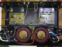
Really like the layout doesn't look like a digital design looks like somebody practically took the time to design really good PCB,s by human effort definitely wont be hard to trace this fault even without a schematic .
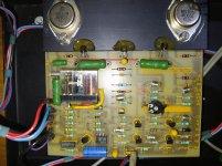
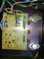
I recognize the output devices , if I was you I would check them for shorts while some like them I don't.
This amplifier is definitely worth working on and check the relay contacts for zero resistance when activated --polystyrene capacitors --- I like the designer right away this guy must have been on EW/WW a quality job -- I am getting jealous !
...Great...so worth fixing then!!
Hoping to put it with a VI PSU and VII Pre that I got going last year!! 🙂
Hoping to put it with a VI PSU and VII Pre that I got going last year!! 🙂
Its "my type of design " straight forward -well laid out -easy to repair not full of stuff I would call "junk " .
When you get your meter out keep us informed .
And according to some sounds good -- don't sell it .
When you get your meter out keep us informed .
And according to some sounds good -- don't sell it .
For such a super simple design on a see through board it will only take an hour or two to draw a circuit. Less if you have it in your hands.
its a simple design a diff pair followed by single stage vas then a pair of drivers the output devices are darlingtons and they are connected to the drivers so as to be inverted ie the load is in the collectors
the ic is to provide speaker protection
I used to retail these very good amplifiers a very well thought out amp
Worth a lot of effort
Trev
the ic is to provide speaker protection
I used to retail these very good amplifiers a very well thought out amp
Worth a lot of effort
Trev
Hope I'm not overdoing the advice here but you really want to find out the output stage quiescent current setting first if there is no available info about it on the net. I would suggest that you disconnect DC from one of the two boards in turn, insulating the resultant flying leads as you go, and see if you can get a single channel operational. There is a good chance that only one channel has failed / is blowing the fuse.
If you get one functioning then record the voltage across each of the largest green wirewounds when warmed up. Then focus on the other board which contains the fault.
If you then fully extract both boards then simple continuity and resistance measurements will allow you to locate the problem components, without even having to reverse engineer the circuit.
I would suspect the following component failures to have been the initial cause:
Mechanical- relays, trimmer pot, solder joints?
Lifetime - Electrolytics (Inc Tants).
Abuse or instability- Output transistors.
The main PSU caps will probably have a date code on them and will be worth discharging and having an ESR and leakage current check. They may not be a problem even if old.
You may be lucky and find the fuse did its job and saved other components from the initial failure. I hope so as its a nice amp.
John
Thanks for replies....This forum is great!! 🙂
Like the idea of generating my own schematic from the board itself....doing it, is another matter of course (having never tried this so far!)
Thanks John....you certainly aren't over-doing it...I suspect this is exactly what I need.
Rather than just 'wade' in and replace components willy-nilly (as I've done before😱 )...I'm hoping to adopt some sort of plan this time!!
post #3 | pic. 1 - burn mark on the rectifier bridge
Hhhmmmnnn....so there is! Will cedrtainly take a look at that.
Thanks🙂
I had some luck repairing my Exposure integrated with some info I found here years ago. Not sure if it’ll help with your IV but I figured I’d share it
Exposure XV | Hifi-Wiki
Exposure XV | Hifi-Wiki
- Home
- Amplifiers
- Solid State
- Exposure IV Schematics/Circuit diagrams please!!