You first would need to define what "underdimensioned" is.could use an underdimensioned trafo
Lots of commercial amps have "underdimensioned" transformers, meaning you cannot continuously draw max power (nearly no one ever does, unless testing with sine waves for max power).
I saw suggestions for transformer power rating ranging from 1x amp max power to 2xamp max power ....
As it has been said here, keep the supply voltage low to save the chips - or at least stay away from the maximum allowed voltage. You will hardly hear any difference between 40 and 80 watts.

How does that relate to the current draw of the amp?80W into 8ohms is 25V RMS or 35V peak.
Current is about 3.2 amps RMS.
lesson started*
ohms law: I= U/ R in DC world, therefore you have to calculate in the AC world the RMS values!
if you forget that a loudspeaker has a complex load (Z) then we can calculate with linear R as your LS.
Urms = Vpeak / sqrt 2
Urms = 35Vpeak / 8 R
Urms = 24,748Vrms ---> 25Vrms
the Voltage peak Vp of a sine wave is the maximum what a amp can deliver. please remind that the power supply get a sag under delivery of energy(voltage and current--->voltage drop)
I rms= U rms / R
I rms = 25Vrms / 8R = 3.125 Arms ---> 3,2Arms ---> max Amps is Arms *1,414 = 3,2*1,414 = 4,512A peak
lesson finished
kr
chris
and additionally:You first would need to define what "underdimensioned" is.
Lots of commercial amps have "underdimensioned" transformers, meaning you cannot continuously draw max power (nearly no one ever does, unless testing with sine waves for max power).
I s yes.
I saw suggestions for trasformer power rating ranging from 1x amp max power to 2xamp max power ....
As it has been said here, keep the supply voltage low to save the chips - or at least stay away from the maximum allowed voltage. You will hardly hear any difference between 40 and 80 watts.
If you think about that your LS is not a linear load with always 8R load then you have to look at your impedance curve of your speaker and normally you will see some frequencies where the LS is maybe 4R ---so your energy must be bigger !!!
if you look in the datasheet of the chip you will see that the maximum Voltage at 4R load is lower.
so keep the voltage what the guys here told you. otherwise your chip get too hot and the maybe brake because of thermal issues. i dont know exactly that chip, but maybe the thermal protection internally is not working so fast and then your speaker can have a damaged too!
correction startedUrms = 35Vpeak / 8 R
Urms = 35Vpeak / 1,41
correction finished 😉
The link in post #12 is already very detailed.
You can just follow him in detail.
Only thing he did not mention was transformer size.
You will find that there is not much difference in price between 150VA and 300VA. Maybe ~ 25%.
I would say 200~250VA is more than enough for normal music listening.
Patrick
You can just follow him in detail.
Only thing he did not mention was transformer size.
You will find that there is not much difference in price between 150VA and 300VA. Maybe ~ 25%.
I would say 200~250VA is more than enough for normal music listening.
Patrick
Indeed it does. Thank you, you’ve been very helpful.Does that answer your question?
2x30V, about 250VA. Gives 42-45VDC depending on house voltage; I mentioned 45 in the OP to keep it simple and at the upper end of the scale.
It depends on how much trouble you want to go to using the existing transformer.
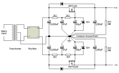
To follow Project 127, you need to drop 10V per rail to ~35V.
This you can do with a MOSFET capacitor multiplier, like that shown in Fig. 5 :
https://sound-au.com/project15.htm
With 35V 8R load, your current is ~4.5A, which means max. dissipation of 45W.
But this only happens when you are clipping the amplifier, i.e. rarely.
Power MOSFET such as IRFP240 will do.
And you will want to replace the 120k resistor with a 39V Zener diode.
But you will need sufficient heatsink for the MOSFET and the 7293 together.
If the above doesn't mean anything to you, then buying a new transformer is the safer option.
Good luck,
Patrick
Last edited:
H
HAYK
Datasheets give curves or formulas to calculate the required power supply. For this chip on page 16 is given with figures 18,19 the necessary information but needs to be clarified. On figure 19 you get the output power vs supply voltage. Example, 35v you get 60W output for 8 ohms 0.5%.. The figure 18 is for 2 chips paralleled but the dissipation of each hence for a single 8 ohms the 4 ohms curve to concider. 35v gives 30w dissipation. The total power needed to be supplied is 90w.
Last edited by a moderator:
Most of these noobs type questions about transformer o/p voltage, max. power output arises due to-
Datasheets mentioning max possible power at max supply voltages, which leads to false belief among new diyers that, they too can also get these extreme power figures (at questionable distortion figures). Please remember , these tests are performed under strict lab condition with proper bench supply, maintaining constant temperatures, resistive loads, pulse testing, etc. Meanwhile the noobs tries the same with his transformers , bridge and caps having poor regulation characteristics on an less than ideal heatsink and thermal paste into real world loads aka speakers.
In short, with chipamps , try using PSU with minimal supply voltages / o/p power from chipamps that you can getaway with.
e.g. I would not go above +/- 25 VDC with a 4 Ohms load which gives me options of 15-0-15 or 18-0-18 VAC , with AC current ratings of 10A or above.
More transformer current capacity , with lower supply voltage (but well above the chipamp's min supply voltage) and lighter loads keeps these chipamps happy. Always remember , at no loads VDC = Vpeak = VAC X 1.41 while the reverse is true for current rating of a transformer
Datasheets should put disclaimers in a layman language, something like - So kids, don't try this at your home or Just do what I say, don't do as I do
Last edited:
Chipamp's max thermal dissipation limits are already tested at 120V, beyond it's real world capabilities
Either use paralleled chipamps or shift to transistors / Class D
Either use paralleled chipamps or shift to transistors / Class D
You won't easily find any class AB chipamps more powerful than tda7293. But you could parallel two (or more) of them!another chip amp
To use a power amplifier IC reliably at or above +/-45V, you should consider LM4702 or LM49830 :
https://audioxpress.com/article/High-End-120W-MOSFET-IC-Driven-Amp
https://www.diyaudio.com/community/threads/lme49830-reference-design-amplifier.399264/
https://www.audiophonics.fr/en/ampl...ier-board-100w-8-ohm-mono-1-unit-p-11190.html
And no, I have not tried myself.
But I can trust Jack 100%.
If this is the route you want to go down, you should contact him ( jackinnj ) directly.
Patrick
- Home
- Amplifiers
- Chip Amps
- Exploding TDA7293, need correct U and I