The crossover for the ESL-57 looks a bit more involved than most DIY designs.
For instance on the tweeter panels, why are there a 150k resistor to the 2 outer tweeter panels plus the 150k//560pf cap?
Do they provide a delay from the center tweeter panel?
There are also 180k resistor between the secondary for the tweeters and winding for the woofer panels and 2x180k resistors for each stator of the woofers.
Finally there is a loading choke.
Just wondering what all this is meant for, and how would perform be affected if any of this was left out.
Hi,
The ESL 57 is actually a three way speaker. 180K resistors to the bass panels is obviously a low pass filter.
The mid range part looks a bit tricky to me. 150K resistors form a low pass filter but 560p cap in parallel to one of resistors is perhaps for frequency response correction?
Finally the treble panel. 270K resistor with 2x560p caps should form a high pass filter, with resistor used mainly for impedance equalization.
I have no idea what loading choke is used for.
Perhaps Quad 57 experts here will provide a better explanation.
Regards,
Lukas.
Not sure if the 180K resistors form a low pass filter. I have other electrostatic tweeters that have 100Meg resistance in series.
What is the spacing of the plates on the woofer? With all those holes, the capacitance can't be much.
What is the spacing of the plates on the woofer? With all those holes, the capacitance can't be much.
Not sure if the 180K resistors form a low pass filter. I have other electrostatic tweeters that have 100Meg resistance in series.
What is the spacing of the plates on the woofer? With all those holes, the capacitance can't be much.
100 Meg resistance can be between EHT supply and the diaphragm and is for different purposes.
Two bass panels with a capacitance of around 500pf in series with 6x180K resistors would form a first order low pass filter at around 300 hz.
f=1/(2*pi*R*C)
For a complete understanding of the ESL-57 crossover as well as its acoustic design I would highly recommend reading the description by Peter Baxandall on pages 169 – 179 of “Loudspeaker and Headphone Handbook”, J. Borwick, Ed.
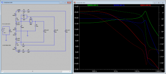
See attached ESL-57 schematic to which I have added the transformer leakage inductance and winding capacitance since they are directly involved in how the crossover works. The values were taken from the Baxandall description…actual production values may vary slightly.
Loading Choke
The purpose of the loading choke was to reduce the magnitude of the impedance peak that occurs at the low-to-mid frequencies of all transformer driven ESLs. It is my understanding that most tube amplifier output stages do not like to be driven at high levels without some amount of loading…internal tube arcing can occur. Without the loading choke, the impedance in the mid-bass region might have been high enough to cause problems with some tube amps of the day. The KLH Nine had a similar loading choke.
For the brief description below to make sense, you must understand that an ESL panel that is small relative to listening distance has a response that naturally rises 6dB/octave when driven from a voltage source; response is flat when driven from a current source.
Bass panel Crossover
Ignoring diaphragm resonance, the bass panels have a natural 6dB/oct rising response. The 6 x 180K resistors in series with the Bass Panel effectively provide current drive above about 300Hz and flatten the response of the bass panels. Looking at it another way, the RC filter puts a 6dB/oct LP filter on the voltage reaching the bass panels. Either way you look at it, the response remains flat until about 1kHz where there is a 2nd order LP network formed by the leakage inductance (46H) and the panel capacitance(400pF).
Below 300Hz, the response would still fall at 6dB/octave. The addition of baffling around the panels and small side wings keeps the response from falling quite this quickly. The diaphragm resonance with Q of 2 or 3 provides equalization for the bottom octave or so.
Tweeter panel Crossover
The sum of the winding capacitance and tweeter panel capacitance in combination with the leakage inductance(145mH) forms a 2nd order LP network just above the audio band at about 24Khz. The resonance is damped by the 150K resistor(junction 9 & 14). This is not immediately obvious, but at 24Khz, the 560pF caps and the mid panel capacitance are essentially short circuits provided the electrical path for the damping. Most other ESLs damp this HF resonance by including a small series resistance of 1-2 ohm in the primary circuit.
The two 560pF caps and 270K resistor were added for production models after serial number 16800. The purpose was to shelve down the drive voltage at lower frequencies by 6dB to avoid arcing the tweeter panel when used with amplifier power > 15W, which was the power level originally designed for.
Mid panel Crossover
The two 150K resistors provide current drive for the mid panel flattening the response as was described in the description of the bass panel crossover. The 560pF cap in parallel with one of the 150K resistors provides a bypass for this resistance so the right amount of damping is applied to the 24kHz tweeter panel crossover resonance. Without it, the response of the tweeter panel would peak up at the top end.
Mid panel & Tweeter Panel Acoustic Crossover
Both the mid panels and tweeter panel are rolled off on the top end (above about 2kHz) due to the curvature of the panels spreading out the radiated HF sound. So the LP for the mid panel is purely acoustic, not electrical. The tweeter panel response is flattened back out using the slightly under-damped resonance at 24kHz.
Attachments
Last edited:
Hi,
Thanks for explanations and especially exact values of transformer parasitic capacitance and leakage inductance.
Now we can start to try simulating the circuit and see what is going on.
Please be aware that there may be errors so corrections are very welcome.
Assumptions in simulation(as I have no exact data):
1) Primary inductance is 100mH based on impedance graph at 30 Hz as published
2) Loading choke is not included as its value is not known.
3) Internal resistance of windings L2, L3 is 2x1KOhm(purely assumption)
4) Internal resistance of winding L1 is 0.1 Ohm(purely assumption)
5) Internal resistance of windings L4, L6 is 0 Ohm(purely assumption)
6) Parasitic capacitance of two outer windings to bass panels is not known, so its not included.
7) Turns ratio for mid/treble windings 2x1:45 each, for bass an additional 2x1:100
Red graph is bass panel, blue is mid and green treble.
Regards,
Lukas.
Attachments
Last edited:
It the total capacitance for both bass panels 400pf and both midranges 200pf?
I don't understand why bypassing the 150k resistance with the 560pf would damp the resonance of the tweeter at 24kHz.
I must acquire this book unless it is online somewhere.
Thanks
I don't understand why bypassing the 150k resistance with the 560pf would damp the resonance of the tweeter at 24kHz.
I must acquire this book unless it is online somewhere.
Thanks
Yes.It the total capacitance for both bass panels 400pf and both midranges 200pf?
At 24Khz, the impedance of the 560pF capacitor and mid panel capacitances are low compared to the remaining 150K resistance. As a simplification, if you replace these capacitances with short circuits(as well as the 560pF caps), you will see that the 150K resistance is shunted across the treble panel providing some damping of the 24kHz resonance.I don't understand why bypassing the 150k resistance with the 560pf would damp the resonance of the tweeter at 24kHz.
I failed to mention that some additional damping comes from resistance in series with the leakage inductance coming from the primary and secondary winding resistance.
The book is still under copyright, although arend-jan used to have a copy of the ESL section from a previous revision available in the technical section of his website.I must acquire this book unless it is online somewhere.
http://www.diyaudio.com/forums/planars-exotics/190023-horn-loaded-electrostatic-9.html#post2610143
@Bazukaz
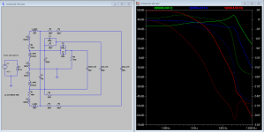
For more accurate modeling of the electrical response, I can fill in a few of your assumptions from the Baxandall notes.
3) Internal resistance of windings L2, L3 is 2x1.5KOhm
4) Internal resistance of winding L1 is 0.6 ohm
5) Internal resistance of windings L4, L6 is 2.35Kohm
6) Parasitic capacitance of two outer windings to bass panels = 70pF
I think the main difference you will see is the increased resistances will damp the 24kHz resonace a bit more than you are currently showing.
Hi,
Simulation updated with new data. The resonance peak at 24 kHz is indeed damped somewhat.
Also LTSpice sim file is attached if anyone is interested in.
Edit : was an error in inductor value L5.
Regards,
Lukas.
Simulation updated with new data. The resonance peak at 24 kHz is indeed damped somewhat.
Also LTSpice sim file is attached if anyone is interested in.
Edit : was an error in inductor value L5.
Regards,
Lukas.
Attachments
Last edited:
These are static capacitances, but how do you take into account the radiation resistance of the air mass load, when the diphragm is moving?
These are static capacitances, but how do you take into account the radiation resistance of the air mass load, when the diphragm is moving?
Interesting question. Radiated energy is a loss, so it should add an additional resistive load in the circuit.
I have no idea what the value is exactly. I think it should be insignificant to overall behavior of the circuit.
If a real world panel is measured IMO there should be some difference in impedance vs frequency when bias is connected or not, from that you could in theory calculate back load resistance.
BTW this also suggests that frequency response will change somewhat depending on bias voltage.
I might be completely wrong as well.
Regards,
Lukas.
Right, since the efficiency is about 0.1%, the radiation loss (that't what we hear) could be neglected.
Right, since the efficiency is about 0.1%, the radiation loss (that't what we hear) could be neglected.
ESL's have very high efficiency but usually low sensitivity.
It is not the same.
The radiating area of ELS element is large, so coupling between the film and air is good and losses are minimal.
The problem is with amplifiers which have to dissipate almost all the power. Class D behave much better here as it can pump energy back into power supply.
Regards,
Lukas.
Last edited:
The ESL57 speaker has a real impedance component, that is the amount of power going into it.
It might have a sensivity of 87dB per Watt at 1m distance.
It might have a sensivity of 87dB per Watt at 1m distance.
87 dB? I suppose it is not more than 82 dB...
According to manufacturer quad esl 57 has a sensitivity of 93 dB.
87 is still reasonable for the tweeter unit after aging but 82 likely indicates a problem.
Regards,
Lukas.
Lukas, I read in the original leaflet (http://www.quadesl.com/graphics/quadGraphics/quaddia.gif) that the maximum output is 93 dB at 6' distance in its full range, which is 50 c/s to 10 Kc/s.
Now originally it was paired with the Quad II valve amplifier rated at 15 W. We can assume that 15 W resulted in 93 dB SPL (synergy between Quad components). 1 W gives about 12 dB less output, that is 81 dB. I don't know if dipoles follow the same law, but point sources give 3 dB increase with halving the measuring distance. So from 6' to 3' it gets 84 dB/1W/1m... Please correct me if my calculations are wrong.
Now originally it was paired with the Quad II valve amplifier rated at 15 W. We can assume that 15 W resulted in 93 dB SPL (synergy between Quad components). 1 W gives about 12 dB less output, that is 81 dB. I don't know if dipoles follow the same law, but point sources give 3 dB increase with halving the measuring distance. So from 6' to 3' it gets 84 dB/1W/1m... Please correct me if my calculations are wrong.
Lukas, I read in the original leaflet (http://www.quadesl.com/graphics/quadGraphics/quaddia.gif) that the maximum output is 93 dB at 6' distance in its full range, which is 50 c/s to 10 Kc/s.
Now originally it was paired with the Quad II valve amplifier rated at 15 W. We can assume that 15 W resulted in 93 dB SPL (synergy between Quad components). 1 W gives about 12 dB less output, that is 81 dB. I don't know if dipoles follow the same law, but point sources give 3 dB increase with halving the measuring distance. So from 6' to 3' it gets 84 dB/1W/1m... Please correct me if my calculations are wrong.
Hi,
As far as I know, point sources drop by 6 and not 3 dB when distance is doubled. Larger planar surfaces drop at about 3 dB.
Indeed, it looks like specification is for max. output:
a) 93 dB@2m for 50 Hz.. 10 kHz
b) 100 dB@2m for 70 Hz.. 7 kHz
We can calculate in a different way as well. Max. input voltage for esl 57 as specified by quad is ~33 Vpk before arcing. Thats around 23.4 Vrms.
Expressed in dB and compared to 2.83V that is :
delta = 20* log(23.4 / 2.83) = 18.35 dB.
So for figure b) we arrive at sensitivity of 100-18.35 ~= 81.65 dB @ 2m
At 1 meter it should be around 85 dB.
However if measured at two meters this equals to a dynamic driver of around 87-88 dB because drop rate is more like 3 dB doubling the distance compared to 6dB for point sources.
Regards,
Lukas.
- Home
- Loudspeakers
- Planars & Exotics
- Explaining the Quad ESL-57 Crossover