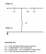
Hello all, could someone explain this highpass XO for me. I know its a 3rd order, but what does R1 do. Dont you normally need 2 resisitors for a pad? And why are C1 and C2 the same value? The crossover is from an Adire kit, that I want to use a different tweeter on. The XO freq is 3500hz.
Attachments
R1 drops the driver level. You need two resistors for a pad only if you don't want the series resistor to change the load impedance. For a parallel crossover, it's a non-issue.
Ok, so I could replace R1 with a pot and be ok then? And is it unusual that both caps have the same value?
The ratio of the caps' value is an indication of the sharpness of the crossover rolloff.
If you're thinking about using this crossover for a different driver, you're heading in a bad direction, potentiometer or no potentiometer. What you need to do is, using the actual impedance and SPL data of the original tweeter, determine what the electrical and acoustic response near the crossover region look like. Then your task is to duplicate it with a different tweeter. Doing it right will not be trivial, but with real data and a good command of a speaker CAD program, it is possible.
If you're thinking about using this crossover for a different driver, you're heading in a bad direction, potentiometer or no potentiometer. What you need to do is, using the actual impedance and SPL data of the original tweeter, determine what the electrical and acoustic response near the crossover region look like. Then your task is to duplicate it with a different tweeter. Doing it right will not be trivial, but with real data and a good command of a speaker CAD program, it is possible.
Ding ding ding! You get the award! He attracted my attention when I was a kid with his role in that classic piece of Danish cinema "Reptilicus."
Now I have to find a new one.
Now I have to find a new one.
What is the reward then? A years free subscription to "my" forum?? Well, I did donate the 20 bucks, allready😀 Any Dane would guess that one😀 😀
Steen😎
Well, it is much prettier than the ugly puppet you had before😱 Made me sick🙄
Steen😎
Well, it is much prettier than the ugly puppet you had before😱 Made me sick🙄
Unless R1 is incorporated in a corrected Rtot for the load, it will also modify the slope of this HP section.
Without knowing the details of rest of the circuit, it is next to impossible to know the exact purpose of R1.
If the sole purpose was to reduce the level of the tweeter, there should be an R2 to ground, to complete an L-pad.
Without knowing the details of rest of the circuit, it is next to impossible to know the exact purpose of R1.
If the sole purpose was to reduce the level of the tweeter, there should be an R2 to ground, to complete an L-pad.
You only need an R2 if you're trying to keep the impedance the same. Why bother to do that in a parallel crossover? Remember, R1 is not an aded component for a modification, it is the resistor that is part of the original design.
that's exactly what i mean....
The filter is undoubtably 3rd order, but R1 will also modify the stop band curve, or the "knee" if you like, so unless you know the details of the total contraption, or more exactly the designers purpose, there is several options to the function of R1
The filter is undoubtably 3rd order, but R1 will also modify the stop band curve, or the "knee" if you like, so unless you know the details of the total contraption, or more exactly the designers purpose, there is several options to the function of R1
- Status
- Not open for further replies.
- Home
- Loudspeakers
- Multi-Way
- Explain this crossover
