looking at this plot:

from here:
https://audioxpress.com/article/test-bench-eighteen-sound-nd3st-1-4-compression-driver
it says "The solid black curve was taken with the ND3ST mounted on the XT1464 horn. The dashed blue curve represents the compression driver without the horn."
this looks like a bass reflex box impedance curve which is produced by port resonance splitting the free air impedance peak of a woofer into two peaks ...
so it seems like there should be some acoustical resonance in the horn splitting the natural impedance peak of the diaphragm ...
but why is the difference with and without the horn so small ?
surely removing a woofer from the box i would expect to see a bigger change in impedance.
what is going on ?
https://www.klippel.de/know-how/measurements/transducer-parameters/electrical-impedance.html
"The diagram shows the electrical impedance for a horn compression driver measured in free air and in vacuum chamber. The impedance measured in vacuum reveals the effect of the electrical and mechanical parts only and removes acoustical resonances."
https://www.klippel.de/fileadmin/kl.../R-D_System/PDF/A7_Vacuum_Measurement_Kit.pdf
Last edited:
Interesting question, and while not knowing exact answers here some keys to interpret: high impedance below voice coil inductance rise is from mechanical motion, the cone has velocity which makes back EMF voltage, which basically makes opposing current in the circuit so net current reduces. As the sweep is with low impedance constant voltage source, impedance peaks when total current is low. This basically means the diaphragm/cone moves "more" with the given input, than at some low impedance frequency. Or, the diaphragn needs less force to move, however you like to imagine it.
So guestion is why diaphragm moves a lot on two frequencies? these peaks are basically resonances, lower is the main resonance due to spring cancelling mass just like with a woofer, but whats the higher one? Another resonance or main resonance split in two like with helmholz resonator? I think it's just another resonance, perhaps air resonates in the gap/phase plug and the diaphragm moves with it with small effort.
When one adds a horn to it there is loading. Whats loading then? the diaphragm gets more effectively in touch with the air mass?, the air in horn becomes part of the system, it's almost coupled witg the diaphragm at sone bandwidth. It seems to show up as a damping effect on the two resonances as reduced impedance peaks (diaphragm moves less than before) and also affects between, helps the diaphragm move more effectively there.
Well, thats just reasoning. Will follow what the science reveals 😀
edit. found one, gedlee post in the ATH thread https://www.diyaudio.com/community/...-design-the-easy-way-ath4.338806/post-6867351 and there is many more posts, search gedlee posts with "peaks"
Last edited:
good link. i think the answer is in there. i will try to understand it when i am less tired.edit. found one, gedlee post in the ATH thread https://www.diyaudio.com/community/...-design-the-easy-way-ath4.338806/post-6867351 and there is many more posts, search gedlee posts with "peaks"
They are BP4 alignments.
if it's a 4th order bandpass:
then why doesn't it have a frequency response of a bandpass box:
https://www.diyaudio.com/community/attachments/untitled-png.739053/
that is if the port is tuned to 1 khz how is it still able to play to 20 khz ?
Last edited:

here is a data sheet for BMS4599HE which shows not only measurements on horn but also in plane wave tube
https://www.bmsspeakers.com/fileadmin/bms-data/product_data_2014/bms_4599nd_preliminary.pdf
why impedance peak is higher in frequency on plane wave tube is beyond me ...
https://www.bmsspeakers.com/fileadmin/bms-data/product_data_2014/bms_4599nd_preliminary.pdf
why impedance peak is higher in frequency on plane wave tube is beyond me ...
so a faster expanding horn would correspond to a shorter port and thus higher bandwidth ? at the expensive of less low frequency extension ?the port is a conical horn that sets its HF BW.
so a horn is basically a wide-band bandpass device ?
here is a data sheet for BMS4599HE which shows not only measurements on horn but also in plane wave tube
Ditto traditional JBL Vs Altec:
Attachments
so a faster expanding horn would correspond to a shorter port and thus higher bandwidth ? at the expensive of less low frequency extension ?
so a horn is basically a wide-band bandpass device ?
Correct
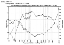
Consider Danley's 511 horn measurement that by design or happenstance highlights where each portion of its total BW is reproduced:
The squiggles in the 4-5 kHz BW is the driver's terminus/horn round to rectangular joint/horn's 2-3 kHz with the rest to its acoustical ~250 Hz BW cutoff.
The squiggles in the 4-5 kHz BW is the driver's terminus/horn round to rectangular joint/horn's 2-3 kHz with the rest to its acoustical ~250 Hz BW cutoff.
Attachments
i like how the brochure says "completely free from resonance"
anyway my brain is shot. i need to sleep. and honestly i don't think i will understand it even when rested.
anyway my brain is shot. i need to sleep. and honestly i don't think i will understand it even when rested.
It is in the sense of high speech intelligibility in the ~100-8 kHz BW when driven with a matching impedance, which is pretty much all the pioneers cared about.
that's the idea is to run the compression drivers to 8 khz, then use something else ... probably bullet supertweeters.
i am thinking these:
https://www.beyma.com/speakers/Fich...kers-data-sheet-compression-tweeter-CP12N.pdf
i used a car audio version of this driver crossed at 7 khz in a car audio system in the past.
the car audio version is double the price because its neodymium and the housing is nicely finished machined aluminum, but i think they're the same exact diaphragm and phase plug except maybe different impedance.
i like this one because it's much wider dispersion above 10 khz than most bullets because the way that clear plastic phase plug works is first it narrows the beam before widening. much like any real compression driver. most bullets never narrow and end up shooting laser beams above 10 khz.
Congratulations!
The topic clearly shows how for the sake of high sensitivity, you have to sacrifice a large part of the quality.
Which is visible on the impedance line.
The topic clearly shows how for the sake of high sensitivity, you have to sacrifice a large part of the quality.
Which is visible on the impedance line.
 I didn't have any real options nor need since they were typically 2 way party speakers w/'full range' driver and occasionally a woofer with a damping resistor for piezos, coffee filter grill to 'critically' damp them/somewhat flatten their polar response.
Attachments
- Home
- Loudspeakers
- Multi-Way
- explain compression driver impedance plots to me