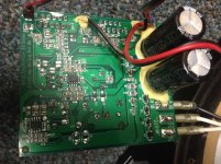
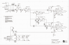
Anyone have any ideas for ways to improve the sound of my Event TR8's? Schematic and photo of the pcb attached. There's a thread here where someone suggests replacing some of the caps:
http://www.diyaudio.com/forums/chip...anual-schematic-event-tr8-active-speaker.html.
Id be interested to know which caps and what would make a good replacement. Open to any other suggestions as well.
About me- total novice, but I have built a distortion pedal and know how to solder. I just thought this could be a fun project and a chance to learn something.
Thanks.
Attachments
I'd swap the TL072 for an LME49720 or OPA1612. Aside from that, I don't see any obvious ways for improvement unless you want to completely redesign the circuit. I'm assuming the capacitors are NP0 ceramics. They tend to be pretty linear.
Tom
Tom
FET inputs with those feedback impedances? At least for U2? (Out of that same family, and in a SOIC8 as well) OPA1652/OPA1642 would be a numerical advantage over what you've got. Not sure audibility, though.
Thanks for the suggestions. Couple of stupid beginner questions, since I would like to learn something too:
1.How do you determine that one opamp is interchangeable with another in a circuit? Are they rated for certain voltages? Have different pinouts? I assume you can't pick opamps at random and expect them all to work in a given circuit.
2.And what do you look for that indicates one chip is superior to another? THD and noise? Something else? Looks like all the ones mentioned have lower distortion and noise values. Looks like the LME49720 has the lowest of all (if I am reading the specs correctly).
3.And a question about the schematic- I see U2a and U2b in the input stage and U3a and U3b in the crossover section, but on the actual pcb I only see the 2 chips (U2 and U3). Is the schematic referring to one chip in 2 places?
4.Also- in the thread I linked, one user specifically mentioned replacing the SMD caps in the signal path with film ones. Does that make sense or is it not worth the trouble? I really don't know much about the difference in capacitor types.
Thanks again and sorry for all the newbie questions, I know I am showing my ignorance here, but I really want to learn this stuff.
1.How do you determine that one opamp is interchangeable with another in a circuit? Are they rated for certain voltages? Have different pinouts? I assume you can't pick opamps at random and expect them all to work in a given circuit.
2.And what do you look for that indicates one chip is superior to another? THD and noise? Something else? Looks like all the ones mentioned have lower distortion and noise values. Looks like the LME49720 has the lowest of all (if I am reading the specs correctly).
3.And a question about the schematic- I see U2a and U2b in the input stage and U3a and U3b in the crossover section, but on the actual pcb I only see the 2 chips (U2 and U3). Is the schematic referring to one chip in 2 places?
4.Also- in the thread I linked, one user specifically mentioned replacing the SMD caps in the signal path with film ones. Does that make sense or is it not worth the trouble? I really don't know much about the difference in capacitor types.
BTW, notice all the ceramic SMD caps in the signal path. I changed them all to nice film caps, the sound has improved, especially the highs. Which always sounded muted on these monitors.
Thanks again and sorry for all the newbie questions, I know I am showing my ignorance here, but I really want to learn this stuff.
Most opamps in DIP or SOIC packages follow a standard pinout.
What to look for? Well. Age plays a factor. The TL072 was invented shortly after dirt was, so odds are that you'll be able to improve on the circuit by swapping a more modern opamp in. The TL072 was also not optimized for audio. It's not a bad opamp, but one can do much better with modern parts.
Which specs? I wish it was as simple as comparing two numbers. There are many tradeoffs. In case of your TL072s, the THD is the most obvious one. Bandwidth is another (higher bandwidth -> higher loop gain within the audio band -> better performance, but also higher chance for instability). Franco or Jung (see the references section of my website) would be good places to start, though beware that you're in for a long learning process.
Tom
Honestly I'd be more worried about U3 than U2. Uh... wait a minute, TL072 driving a 2k1 load? What the heck were they thinking? Yeah, U2 needs something with a lot more "oomph". You can usually recognize parts like that by their not-ultra-low current draw for their bandwidth, so maybe rather OPA1652 than 1642. I'd actually prefer something with load immunity at least equal to an NE5532, unfortunately that one has some input stage issues.
U3 should also be able to take a bipolar of moderate Ib like OPA1612 (note an improvement in hiss is expected with a lower-noise part, though further improvements may require inspecting the entire gain structure). Actually same would go for U2 if swapping out the silly-high R11 for more like 10k, though there may still be some output DC offset at the woofer.
Local rail decoupling for the opamps is also advised. TL072s are relatively slow and well-behaved still, faster parts not necessarily so.
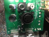
Oh, and the XLR input is wired up wrong ("Pin 1 problem"). Pin 1 must be disconnected from circuit ground and instead go to chassis ground, i.e. where the shell already connects. Use the shortest, fattest connection possible. Also check routing at the TRS input ground. It looks like chassis ground and circuit ground connect there, but make sure that first input ground connects to chassis ground and then circuit ground to chassis ground, rather than input ground to circuit ground and then both going to chassis ground somewhere.
EDIT: Oh, wait, there's 3 different "grounds" in this one - chassis ground (XLR shell), power supply / power stage ground (now XLR pin 1), and small-signal ground. Current pin 1 routing may actually be OK since it goes to power supply ground rather than (vulnerable) small-signal ground. Still, a direct, low-inductance connection from XLR pin 1 and TRS sleeve to chassis remains the best choice WRT signal integrity, allowing the cable shield to connect to the equipment housing to extend the Faraday cage. (Read Bruno Putzeys on pin 1 problems and his "G-Word" whitepaper for details.)
U3 should also be able to take a bipolar of moderate Ib like OPA1612 (note an improvement in hiss is expected with a lower-noise part, though further improvements may require inspecting the entire gain structure). Actually same would go for U2 if swapping out the silly-high R11 for more like 10k, though there may still be some output DC offset at the woofer.
Local rail decoupling for the opamps is also advised. TL072s are relatively slow and well-behaved still, faster parts not necessarily so.
Oh, and the XLR input is wired up wrong ("Pin 1 problem"). Pin 1 must be disconnected from circuit ground and instead go to chassis ground, i.e. where the shell already connects. Use the shortest, fattest connection possible. Also check routing at the TRS input ground. It looks like chassis ground and circuit ground connect there, but make sure that first input ground connects to chassis ground and then circuit ground to chassis ground, rather than input ground to circuit ground and then both going to chassis ground somewhere.
EDIT: Oh, wait, there's 3 different "grounds" in this one - chassis ground (XLR shell), power supply / power stage ground (now XLR pin 1), and small-signal ground. Current pin 1 routing may actually be OK since it goes to power supply ground rather than (vulnerable) small-signal ground. Still, a direct, low-inductance connection from XLR pin 1 and TRS sleeve to chassis remains the best choice WRT signal integrity, allowing the cable shield to connect to the equipment housing to extend the Faraday cage. (Read Bruno Putzeys on pin 1 problems and his "G-Word" whitepaper for details.)
Last edited:
IIRC the 1642 is linear into heavier loads than the 1652 (both clearly better than a poor TL072), so it'd probably get the nod at the U2 location. I haven't done a good look at the opamp landscape to say what other parts might applicable for that part. Current noise/DC offset around those 20k's, and FET-inputs RF immunity has me leaning more towards a FET input than a BJT for U2.
I agree on U3--the recommended BJT-input opamps should work quite well.
I agree on U3--the recommended BJT-input opamps should work quite well.
Thanks for all the suggestions.
Please someone tell me if I have this straight. The contenders are:
For U3?
LME49720
OPA1612
For U2?
OPA1652
OPA1642
I'm a little confused about U2 v. U3 and whether certain chips are appropriate for each or if they are interchangeable. Can someone explain?
sgrossklass, could you elaborate on rail decoupling? Not something I'm familiar with. And about the audio grounds - do you mean I should tie pin 1 to the outer shell of the XLR connector?
No one has mentioned anything about swapping out caps, so I'll assume it's not something that's worthwhile?
One more question- are there any safety concerns getting into this? Do I need to be careful around the capacitors or anything?
Thanks for all the help guys. I'm learning a lot here.
Opamp performance is a complex mix of a whole bunch of different factors, including distortion mechanisms. (Some people have spent many hours staring at measurement results such as those obtained by Samuel Groner.) The main factors considered here are:I'm a little confused about U2 v. U3 and whether certain chips are appropriate for each or if they are interchangeable. Can someone explain?
Output driving - how much does distortion worsen when driving loads? (At high levels, TL07x realistically should not be loaded with less than 10-20k. So that 2k + 100R loading gets a frown here, especially if your input signal is hot, as that is all it depends on.)
Input bias current - could cause significant output offset if DC resistances at +/-in are mismatched. (Hence my remark re: R11.) Keep in mind this would be amplifier by woofer amplifier gain. FET input or bias current compensated parts do better in such cases.
Input impedance distortion - Usually a result of input capacitance nonlinearity and potentially bias current nonlinearity (for bipolar input stages at highish tail current). Usually not a strength of JFET input opamps, but it seems OPA1642 et.al. actually are excellent in this regard. Effect depends on behavior of nonlinearity and AC impedance mismatch.
You want to keep your supply rails at a lowish impedance up to several MHz. I did miss the small decoupling caps though (C18-20, C26-28), those should get the job done here.sgrossklass, could you elaborate on rail decoupling? Not something I'm familiar with.
Indeed, after disconnecting pin 1 from the existing trace obviously. (It's a PCB-mount connector, so a cut in the trace and a short, fat piece of wire between the shell and pin 1 solder joints is likely to be the most elegant solution. Let's hope you don't have to desolder the connector.) "Shield" would be a better term than "ground" in this case, since it's obviously a balanced connector.And about the audio grounds - do you mean I should tie pin 1 to the outer shell of the XLR connector?
Since TRS connects in parallel, a similar rework may be needed, depending on what routing looks like now.
Good point, I missed that. Those in the signal path appear to be surface mount MLCC ceramics. They're rated 100V and higher and probably X7R or similar, so nonlinearity should not be too bad. Depends on how loud you're listening. Still, they're in the crossover, so if you can find film capacitors in a similar footprint (they do make surface mount ones these days, would look less messy than leaded ones)...No one has mentioned anything about swapping out caps, so I'll assume it's not something that's worthwhile?
Re: the big 4700/50V caps, I'm not sure what brand that is. "XC", looks like some Chinese manufacturer. Not exactly oversized either. I'd look at some quality Japanese / Western / Rubycon (TW) jobs to replace those, work out the mechanics to see whether you can fit 6800 or even 8200 µF.
Not particularly, it's all secondary side, so not like in a SMPS or anything. I'd expect like +/- 35 V max there, and the opamps should have most of that drained reasonably quickly after turning off power. Still you can discharge the big ones with a ~1k resistor if you want to be absolutely sure.One more question- are there any safety concerns getting into this? Do I need to be careful around the capacitors or anything?
Thanks for the detailed response. Very helpful.
Should I consider changing any of the resistor values as well, or will a better performing opamp take care of these issues?
Really displaying my ignorance here - how do I know which caps are in the signal path? I'm still learning how to read schematics.
Output driving - how much does distortion worsen when driving loads? (At high levels, TL07x realistically should not be loaded with less than 10-20k. So that 2k + 100R loading gets a frown here, especially if your input signal is hot, as that is all it depends on.)
Input bias current - could cause significant output offset if DC resistances at +/-in are mismatched. (Hence my remark re: R11.) Keep in mind this would be amplifier by woofer amplifier gain. FET input or bias current compensated parts do better in such cases.
Should I consider changing any of the resistor values as well, or will a better performing opamp take care of these issues?
Good point, I missed that. Those in the signal path appear to be surface mount MLCC ceramics. They're rated 100V and higher and probably X7R or similar, so nonlinearity should not be too bad. Depends on how loud you're listening. Still, they're in the crossover, so if you can find film capacitors in a similar footprint (they do make surface mount ones these days, would look less messy than leaded ones)...
Re: the big 4700/50V caps, I'm not sure what brand that is. "XC", looks like some Chinese manufacturer. Not exactly oversized either. I'd look at some quality Japanese / Western / Rubycon (TW) jobs to replace those, work out the mechanics to see whether you can fit 6800 or even 8200 µF.
Really displaying my ignorance here - how do I know which caps are in the signal path? I'm still learning how to read schematics.
I wouldn't monkey with the resistors. That's getting more advanced than it's worth fighting with, especially if you're not super comfortable working around SMT. And the caps look fine. As Sgrossk
Trace the input signal through the amplifier block. The capacitors it directly touches would be one (by simplest definition) that are in the signal path. C2, C6, C7, for example are in the signal path, whereas we'd say C18-20 are power supply bypass, and C10-C11 are your primary power supply caps. Those are the ones that sgrossklass is suggesting to replace with larger values (from no-nonsense manufacturers).
Trace the input signal through the amplifier block. The capacitors it directly touches would be one (by simplest definition) that are in the signal path. C2, C6, C7, for example are in the signal path, whereas we'd say C18-20 are power supply bypass, and C10-C11 are your primary power supply caps. Those are the ones that sgrossklass is suggesting to replace with larger values (from no-nonsense manufacturers).
Hi guys, I'm gonna go ahead and buy some components for this project. Just a few more questions:
When searching for opamps on mouser, I found they had designations like AID, AIDR, AIDGKT, and AIDGKR. Just wondering what this means. Some come in different "packages" and I assume I'm looking for SOIC-8?
For the large power supply caps, would something like this be appropriate?:
63MXG8200MEFCSN30X40 Rubycon | Capacitors | DigiKey
As for other caps in the signal path, I think I'll try swapping those out too - I found these film surface mount types. Would these work/ be an improvement? Do I just need to match the capacitance and the voltage rating (DC) for each cap?
SMDID03100TA00MS00 WIMA | Mouser
Am I right then in assuming that any capacitor not in the power supply section of the schematic is in the signal path?
Actually looks like that Rubycon capacitor can't be found in small quantities. There are several on mouser from Cornell Dubliner, UCC, and Nichicon:
Find Electronic Components | Mouser
What's important as far as specs? Voltage rating just needs to be equal to or greater than the part its replacing?
Find Electronic Components | Mouser
What's important as far as specs? Voltage rating just needs to be equal to or greater than the part its replacing?
- Status
- Not open for further replies.
- Home
- Amplifiers
- Chip Amps
- Event TR8 mods? (newbie question)