Hi Andrew #18. Re: Pmax rating of NFB resistors. Right! I can't be sure whether it was Ed Cherry or maybe Robert Cordell but I do recall one of the gurus making this point at least 40 yrs ago for a published diy circuit with a comment along the lines of: "An amp' can't be more linear than its feedback net work."
Cheers Jonathan
Cheers Jonathan
Very nice THD. You're using output inclusive compensation, right ?
Regarding your resistors, since they introduce distortion in the feedback network, feedback cannot correct it, and also there is no frequency-dependent amount of feedback to apply.
Therefore, if you do the same test at different frequencies... say 10k and 1k...
If both give same results: the value of your resistor depends on voltage. It happens. They don't specify ppm/volt but you can bet it isn't zero...
If 1kHz has 10x more distortion than 10kHz: you get a time-dependent effect due to thermal mass, self heating, and ppm/°C.
Last edited:
Not as I understand output inclusive compensation, where the output stage compensation is tied back to the VAS. I'm compensating input and VAS, then adding Cdom in the feedback path - very conventional.
I'm having a lot of trouble getting decent 10KHz distortion figures - I have an LT AN67 oscillator for 1KHz, which is what I'm using. I initially figured that I could use a soundcard for 10KHz (my mac with a 10KHz tone generated from audacity), but it's got very high noise levels from 20K up. I think I'm going to have to build another AN67 oscillator to do it properly.
I'm having a lot of trouble getting decent 10KHz distortion figures - I have an LT AN67 oscillator for 1KHz, which is what I'm using. I initially figured that I could use a soundcard for 10KHz (my mac with a 10KHz tone generated from audacity), but it's got very high noise levels from 20K up. I think I'm going to have to build another AN67 oscillator to do it properly.
Last edited:
THD at 10Khz is in principle 100x higher than at 1KHz, unless that the circuit has poor linearity to start with, at wich point THD at 1KHz will be relatively high and the distorsion increasing apparently linearly with frequency being wrongly interpreted as a sign of good design while it s likely the opposite.
On the numbers themselves, and given the state of the technology, sub ppm THD at 1KHz is doable even with standard topologies, but such levels at 10KHz can be achieved only with NDFL and other such tricky designs.
I m of course talking of something that has good stability, otherwise with a BIG inductance at the output it s not difficult to get such low rates...
THD at 10Khz is in principle 100x higher than at 1KHz, unless that the circuit has poor linearity to start with, at wich point THD at 1KHz will be relatively high and the distorsion increasing apparently linearly with frequency being wrongly interpreted as a sign of good design while it s likely the opposite.
On the numbers themselves, and given the state of the technology, sub ppm THD at 1KHz is doable even with standard topologies, but such levels at 10KHz can be achieved only with NDFL and other such tricky designs.
I m of course talking of something that has good stability, otherwise with a BIG inductance at the output it s not difficult to get such low rates...
How do you figure the 100x difference? Cdom sets 20dB/decade reduction in OLG, so there's therefore 20dB less gain available at 10KHz than at 1KHz, therefore (all else being equal), 10KHz THD will be 10x higher.
This is borne out by my measurements thus far, at least in principle. Even with the mac as a source at 10KHz, I'm seeing 0.002-0.003%, which is a little more than 10x my measurements at 1K, but certainly not 100x higher.
Also, I'm already sub-1ppm, from ~1W up to 25W. Outside there I'm either noise-limited or starting to clip.
Last edited:
Thick film devices are known to have very high voltage coefficients - i.e. the resistance changes with the voltage across them. Its a separate mechanism from resistance change due to temperature increase. Other problems with thick film are noise modulation - same as carbon comp resistors.
Bruce Hoffer from AP file:///C:/Users/user/Downloads/Designing_for_Ultra-Low_THD_N.pdf
Thick film - no good for audio! See Douglas Self SSAD for AP plots showing this
Thin film - from 0805 up the performance is good and from 1206 upwards its as good as a 1/2 watt leaded metal film.
So, select the feedback resistor on these key parameters
1. low tempco - worth spending extra for 25ppm or better
2. select a low voltage coeff resistor type - so thin film for SMD; standard leaded MF are very good; If using SMD, stick with 1206 thin film if you want the same performance as a leaded 1/2 watt device wrt distortion
3. size the resistor correctly for Pdmax. no point going overboard but its no help if you end up with a device that's running hot due to self-heating
4. A CFA will probably demand a higher wattage feedback resistor than a similar power VFA because the CFA feedback resistor will be much lower = greater current and therefore dissipation. For a 100W CFA, I use 2.5W made up of 5 off 0.5 W resistors. The worst case RMS power dissipation is 1.875 Watts.
I only use thick film on digital boards. E24 1206 Thin films at Mouser are about 1 or 2 cents in quantities of 100 up+
Last edited:
Did you buy an AN67 kit, wondering which one since I'm also thinking of building one?
Yes, an EOSC10Kv3. Frex (on here) is selling PCBs. It's a very nice bit of kit.
How do you figure the 100x difference? Cdom sets 20dB/decade reduction in OLG, so there's therefore 20dB less gain available at 10KHz than at 1KHz, therefore (all else being equal), 10KHz THD will be 10x higher.
There s 20dB lower NFB but this also imply that the input stage has to provide a signal that has 20dB higher magnitude, and its distorsion will increase accordingly, also the VAS and OS linearities decrease with frequency
This is borne out by my measurements thus far, at least in principle. Even with the mac as a source at 10KHz, I'm seeing 0.002-0.003%, which is a little more than 10x my measurements at 1K, but certainly not 100x higher.
That must be at quite low power...
Btw, i just made a sim of a discrete 741, aka blameless amp, and the HD residuals are at 20uV at 1KHz and up to 1.5mV at 10KHz, output level being 40V pk.
That must be at quite low power...
Btw, i just made a sim of a discrete 741, aka blameless amp, and the HD residuals are at 20uV at 1KHz and up to 1.5mV at 10KHz, output level being 40V pk.
Yeah - only 5W.
Adding a folded cascode to the first stage and current-source second-stage loads gets this topology (which is entirely conventional) down to 10KHz 1ppm, at least in sim. See http://www.diyaudio.com/forums/soli...ing-aem6000-design-ppm-thd-2.html#post4936930
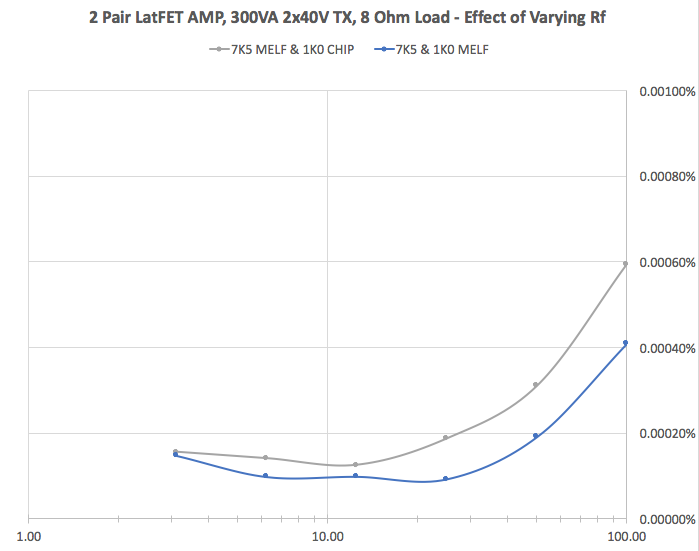
So, there's another resistor in this feedback network. That's also a thick-film chip resistor. Swapping it for a MELF has a much less dramatic effect on distortion, but definitely measurable, which makes sense as the voltages on this resistor are much smaller.
There's two more resistors on the other side of the input which are used to set bandwidth. The 750R in series is already a MELF, for no good reason other than that's what I had, but the 100K in parallel with the input is a thick film. I'll swap it, but don't expect any measurable improvement, as the divider here is very small.
There's two more resistors on the other side of the input which are used to set bandwidth. The 750R in series is already a MELF, for no good reason other than that's what I had, but the 100K in parallel with the input is a thick film. I'll swap it, but don't expect any measurable improvement, as the divider here is very small.
Last edited:

Out of curiosity i made a few sims of the simplified version and without cascodes on the dual differential stage since these change about nothing to the circuit linearity.
For 12.5V Pk/8R THD at 1KHz is indeed very low with H2/H3 being dominant at 12uV each, but at 10KHz it s much higher at 400uV., dunno if i made a mistake, FTR phase margin is 32° at unity gain frequency (6.6MHz) and gain margin is 13db at unity loop gain (2.4MHz).
For 12.5V Pk/8R THD at 1KHz is indeed very low with H2/H3 being dominant at 12uV each, but at 10KHz it s much higher at 400uV., dunno if i made a mistake, FTR phase margin is 32° at unity gain frequency (6.6MHz) and gain margin is 13db at unity loop gain (2.4MHz).
I just posted into a PASS thread that I knew about this a long time ago and guessed it was from before I joined this Forum in 2004.Hi Andrew #18. Re: Pmax rating of NFB resistors. Right! I can't be sure whether it was Ed Cherry or maybe Robert Cordell but I do recall one of the gurus making this point at least 40 yrs ago for a published diy circuit with a comment along the lines of: "An amp' can't be more linear than its feedback net work."
Cheers Jonathan
You are confirming that it was even longer ago that this was discussed or caution issued.
Just pulled apart my 1 KHz AN67 source and changed it to 10 KHz. Lesson for today is that it will_not_work_reliably unless I clean it, clean it again, clean it a third time with isopropyl, blow it carefully dry, then bake it for a while to ensure there's no moisture left before setting the loop gain.
So, that done, we have yet another plot. I'm calling this amplifier done.
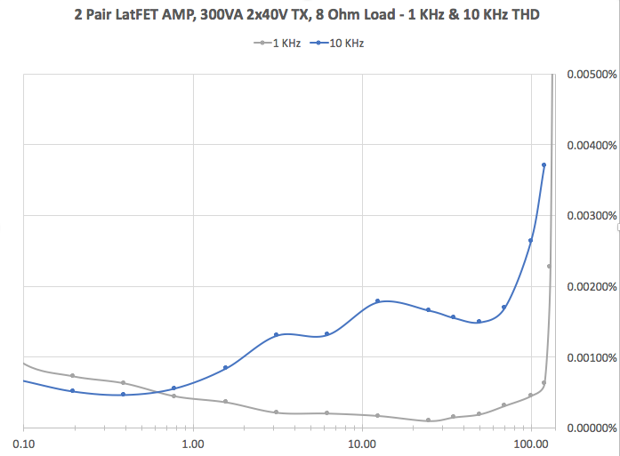
THD at 10KHz is about 10x that at 1 KHz in the region where we're not noise limited. This is to be expected, given the 20dB reduction in available loop gain with which to correct the error.
An interesting feature of these graphs is at the bottom end, where I'm noise limited. 10 KHz THD is a tad better than 1 KHz. I'm thinking this is down to being further away from the 50 Hz rubbish that gets in at lower frequencies, dropping the noise floor on my analyser.
So, that done, we have yet another plot. I'm calling this amplifier done.
THD at 10KHz is about 10x that at 1 KHz in the region where we're not noise limited. This is to be expected, given the 20dB reduction in available loop gain with which to correct the error.
An interesting feature of these graphs is at the bottom end, where I'm noise limited. 10 KHz THD is a tad better than 1 KHz. I'm thinking this is down to being further away from the 50 Hz rubbish that gets in at lower frequencies, dropping the noise floor on my analyser.
 congrats suzyj - this is *VERY* impressive indeed ! Well done and time to box it up and enjoy !!
- Status
- Not open for further replies.
- Home
- Amplifiers
- Solid State
- Even order distortion in symmetrical amp