A couple of years ago I made a CBT of waveguides and posted it here:
https://www.diyaudio.com/community/...-with-waveguide-and-cbt-shading.266417/page-4
I wanted to evaluate that again, but the thread above isn't mine, so thought I'd post a new thread to keep things organized.
A CBT of waveguides is exactly what it sounds like: you take a bunch of waveguides, stack them vertically, and then you evaluate how they perform when compared to a conventional CBT array, which generally uses direct radiators.
For those who do not see a page four, you may have non-standard page settings. Try post# 61..
https://www.diyaudio.com/community/...waveguide-and-cbt-shading.266417/post-6778146
https://www.diyaudio.com/community/...waveguide-and-cbt-shading.266417/post-6778146
Last edited:
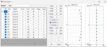
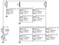
First up is an eleven element CBT array, using Tymphany TC7s
This CBT is comprised of a 45 degree arc, measuring 80cm in height.
Most of the Keele and JBL CBTs leverage the floor or ceiling as a mirror, so that they behave as if they're twice as tall as they really are
But I'm not sure if I want this array on the floor, and I am not aware of any way to simulate the "mirroring" effect in VituixCAD
There are eleven elements in the array, and the shading is fairly straightforward
Attachments
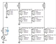
Here's the crossover and the resulting impedance. These things are ridiculously easy to drive. The crossover is pretty affordable too, it's four resistors and one capacitor.
Attachments
![2023-07-24 22_51_04-Xara Photo & Graphic Designer - [Untitled26 _].jpg](/community/data/attachments/1104/1104272-b474d4d2fd675a8fd28bd1ee60bfbb2b.jpg?hash=tHTU0v1nWo)
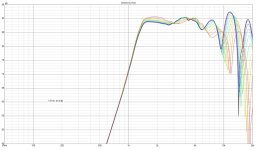
Here's the horizontal response of the CBT array described in the last few posts, and a single TC7
As you can see, on the horizontal axis, the CBT array basically behaves like a single driver.
As you can see, on the horizontal axis, the CBT array basically behaves like a single driver.
Attachments
Thanks! Hmm, don't recall changing this setting, but I only have two pages, so what's standard? TIAFor those who do not see a page four, you may have non-standard page settings. Try post# 61..
Convex, outward curve in the side view pictures.It is concave as seen from the listener?
It should currently be 20 posts per page, it used to be 10. You seem to be on 50 as am I.what's standard? TIA

It is concave as seen from the listener?
//
Dangit!
Thanks for catching that, I just started using that feature yesterday
Looks like I wasted quite a bit of time :O
Attachments
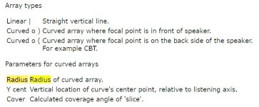
Isnt the "o" in the setting the head and then the parenthesis the CBT?Convex, outward curve in the side view pictures.
Look at post #3
//
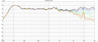
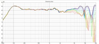
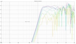
Here's the same array, but fixed per TNT
the unlabeled sim is the horizontal response of a focused and shaded array
The labeled sim is the exact same thing, but a CBT (IE, it's convex and shaded)
It's interesting to see how the focused array performs quite a bit better at high frequencies. This is because the pathlength difference between the elements in the convex array are longer than in the concave array
Attachments

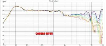
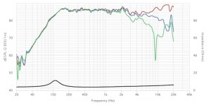
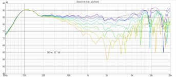
Here's the convex array, simulated on the vertical and horizontal axis
As before, it's eleven elements, it's a CBT, and it measures 80cm tall
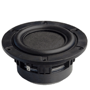
Drivers are Tymphany TC7
I made some changes to the crossover to flatten things out as much as possible, but it still isn't as flat as a concave shaded array
But there's plenty of efficiency, so it's straightforward to EQ it flat. It can even be passive, still no need to go active, because there's no DSP delay here
As before, it's eleven elements, it's a CBT, and it measures 80cm tall
Drivers are Tymphany TC7
I made some changes to the crossover to flatten things out as much as possible, but it still isn't as flat as a concave shaded array
But there's plenty of efficiency, so it's straightforward to EQ it flat. It can even be passive, still no need to go active, because there's no DSP delay here
Attachments
-
 2023-07-25 01_14_15-VituixCAD_ C__Users_johnv_Documents_spkrstuf_jul 24 2023 - full range cbt ...jpg140.6 KB · Views: 69
 -
 2023-07-25 01_13_12-VituixCAD_ C__Users_johnv_Documents_spkrstuf_jul 24 2023 - full range cbt ...jpg129.3 KB · Views: 69
 -
 2023-07-25 01_12_18-VituixCAD_ C__Users_johnv_Documents_spkrstuf_jul 24 2023 - full range cbt ...jpg67.5 KB · Views: 69
??? Regardless, PB clarifies..........Isnt the "o" in the setting the head and then the parenthesis the CBT?
Look at post #3
//
The idea of this thread was to see if a CBT of waveguides offered advantages over a CBT of full ranges.
I thought this could have two advantages:
1) when you use a CBT of full ranges, like the Dayton Epique CBT24, the high frequencies aren't optimum because the high frequency performance of a full range is bested by a "real" tweeter, generally
2) if you go with a CBT of two-ways, like the CBT36, you need an absolute TON of tweeters. The CBT36 uses 72 tweeters per channel!
So my thought was "maybe if you put fewer tweeters on a waveguide, you could narrow the directivity enough that they won't interfere with each other."
In this simulation, I used the exact same number of drivers as the last sim, and the exact same locations and dimensions, but I used a horn loaded tweeter instead, the Tymphany BC25SC06.
I'd argue that there isn't an obvious winner in this competition:
* The array of horn loaded tweeters is more sensitive (no big surprise)
* the array of full ranges plays way lower (no big surprise)
* the off-axis performance of the full ranges is superior, especially in the range where the waveguide no longer provides directivity control (from 1khz to 6750hz)
Someone over on audiosciencereview published a CBT of planar full ranges, and that probably a smart option. It looks like the CBT really likes drivers with narrow directivity.
If I had a couple of days to kill, it would be interesting to try and 3D print a phase plug which produces a flat wavefront from a full range driver. I don't think there's anything like that for sale; the people who manufacture full-range drivers generally want wide dispersion not narrow dispersion. The ideal way to get a flat wavefront from a full range would be a radiator that's a rigid disc.
BMRs have a disc radiator, but it's not rigid, and the entire idea behind BMRs is that their vibrational modes produce a wide beam from a flat diaphragm. One possibility might be to bond some carbon fiber to the existing cone to make it stiff.
That leaves a phase plug as the most obvious solution. Basically equalize the pathlengths of a full range to flatten out the wavefront.
NOTE:
In this simulation, the output level looks weirdly low for an array of horn tweeters. The reason for this is because I used the crossover filter to offset the rise in output that happens when the wavelengths become larger than the radiator. Basically, at high frequencies the tweeters do not sum constructively (because the wavelengths are so short) and you get a crazy polar response. At lower frequencies, the tweeters DO sum constructively, and you get a rise in output as the frequencies get lower and lower. To get a response that's flat overall, you have to compensate for that.
Attachments
- Home
- Loudspeakers
- Multi-Way
- Evaluation of a CBT of Waveguides