It's that opaque ampule shape in the middle. Two Raytheon compact tubes. Probably used on 1960's jet fighters. 🙂
Interesting - never seen it before. I thought they were some boutique or Russian caps. 😕
This is what I am interested in. I don't really need another headamp but would like to try this one sometime in future. I'm just drawn to simple schematics/designs that work/sound good - and this one seems to fit that bill.Listening not bad with high impedance headphones (HD600, DT880 600R), lets say more bass as Wayne´s HPA supplied with +/-18VDC?!
It is very simple and you can simplify further by replacing the active LM317HV CCS (which technically adds an opamp with 20 transistors to the circuit) with a simple 5w 220R wire-wound. There is possibility of quadrupling the output power (passively) by replacing the resistor CCS with a properly sized inductor. A large many tens of mH low DCR one (a big spool of magnet wire works) or an air gapped steel core one for compactness. The reactive nature of the inductor amplifies the amount of voltage swing for more power.
I just had a look at the amp in the op. With 20v at 130ma heaters, you could use them as load for the mosfets... That's what was done in the famous Melos sha1. It works surprisingly well.
The 7370 draws 260mA at 20V with the two heaters in series. You could ground the CT and give both halves of the heater 20V. I thought about trying this (just like Millet does it with the SSMH, too) but I was also keen on trying to direct couple the stages and was worried about how consistent the heaters would be. If I build another one of these, I'll probably give this a shot (maybe cap coupled). Could be a little more compact by eliminating heatsinks.
The 417A is a 20V 100mA heater and I thought about using two halves in parallel the same way, but the plate curves didn't look like it would like the low B+ (even in parallel).
The 417A is a 20V 100mA heater and I thought about using two halves in parallel the same way, but the plate curves didn't look like it would like the low B+ (even in parallel).
You would still need sinks on main MOSFETs. Would not the variying pulsing current in the heaters, in this way perhaps drive some unwanted feedback? I guess one could put such big caps to filter it and make it very steady though.
Yes, eliminating some of the heatsinks is what I should have written. Still needed for the mosfets.
As far as feedback, only trying it would give one a good idea. Heaters on indirectly heated tubes are frequently run AC silently but in some cases you can get some of the mains frequency in the output. Whether that is the heater/cathode interaction or just wiring best practice is another question.
In this hypothetical case, we would have an inverted signal at the cathode, so nfb. Not necessarily a deal killer even if there is some small effect.
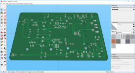
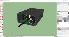
Here, after successful test, 1AD4/IRF510 Headphone Amplifier.
I will order a batch of 5.
JP
I will order a batch of 5.
JP
Attachments

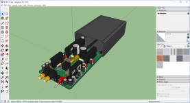

Nice work JP. What DC-DC step up are you using? Note that you need to use the LM317HV for the CCS of the SE Class A output stage. I tried regular LM317 and it did not work. Very finished design.

I bet with the 24V supply it will be ok.
I think the issue with the Estudiante and 'regular LM317 was at start up. The gate would see the full supply voltage because the tube heaters had not warmed up. This was essentially dumping all 48V across the CCS and the supply was probably cycling at the same time because of the heater current draw. I've seen builds work without the 'HV' but it probably comes down to the supply used.
I updated all of my docs to specify LM317HV. It was listed in places (that's the part I built my own with because I had them) but I didn't reinforce the importance.
At any rate, JP's project (awesome job, by the way) shouldn't have the same issue with the regular LM317. I'm interested to see the rest.
You know you could easily make it portable with just a couple of standard 12V car batteries in series 🙂
Nice work JP. What DC-DC step up are you using? Note that you need to use the LM317HV for the CCS of the SE Class A output stage. I tried regular LM317 and it did not work. Very finished design.
Hello xrk971. A constant current source [CCS] which uses LM317 can oscillate unexpectedly. Consider adding a Zobel [10 Ohm resistor in series with 0.1uF] like that found in power amps between the output of LM317 and ground to remedy!
Best
Anton.
I think the issue was the 48v supply - LM317 is not rated that high and it probably latched into a safe mode.
Cathode Resistor Clarification
Thank you SodaMod for presenting this project and all your nice tutorials on the wtfamps.com web site.
I'm a tube noob, so please help me understand this: Since the target quiescent operating point is -1 volt DC on the grid, to created 2.5mA of plate current, it seems like the cathode resistor should be something closer to 400 Ohms instead of the 750 Ohms shown on the schematic? Please set me straight.

Your observation is not flawed, Obe1! The plate curve calc suggests that 400 ohms would put us where we want to be (1V/2.5ma).
Our goal is to get the anode to sit around half the supply voltage so that the output stage can swing up and down with signal. In practice, I found that a 750 ohm resistor put my anode at 24V. I didn't explain this anywhere on the page though. I'll revisit my write up and maybe add some additional voltage check measurements (probably helpful for others, too).
Here is a detail of the different cathode resistors:
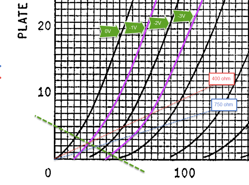
You can see that although the difference in value appears to be large, the anode voltage (found on the green dashed line) varies less than you might expect (between dashed red and dashed blue).
Our goal is to get the anode to sit around half the supply voltage so that the output stage can swing up and down with signal. In practice, I found that a 750 ohm resistor put my anode at 24V. I didn't explain this anywhere on the page though. I'll revisit my write up and maybe add some additional voltage check measurements (probably helpful for others, too).
Here is a detail of the different cathode resistors:
You can see that although the difference in value appears to be large, the anode voltage (found on the green dashed line) varies less than you might expect (between dashed red and dashed blue).
Thank you Sodacos for your prompt and comprehensive responce to my inquiry.
It all makes much more sense now.
My lesson of the day: Creating a design using vacuum tubes is like working with any other component. When you wish to push it close to it's specified boundaries, science & logic must accept some assistance from a strong dose of thaumaturgy, a pinch of good luck, and possibly a bigger hammer.
Salud!
Very simple yet very interesting project. Just one question: what is the heat discipation of mosfets and lm317s in this amp?
We have a supply voltage of 48V and about 100mA through each channel with a 12 ohm set resistor on the LM317HV. This means we have about 5W in each channel or 2.5W per TO220 device. Around 10W total in a stereo amp.
I used a single large heatsink salvaged from an old subwoofer amp, but I didn't have a C/W rating. I wouldn't hesitate to use something like the Mini Dissipante chassis from the diyAudio Store. Individual heatsinks rated around 5 degrees C/W or lower would also be fine.
I used a single large heatsink salvaged from an old subwoofer amp, but I didn't have a C/W rating. I wouldn't hesitate to use something like the Mini Dissipante chassis from the diyAudio Store. Individual heatsinks rated around 5 degrees C/W or lower would also be fine.
- Status
- Not open for further replies.
- Home
- Amplifiers
- Headphone Systems
- "Estudiante" Hybrid (7370 + MOSFET)