Howdy Folks,
Long time no see, hope you are all doing well!
I wonder if you can help me figure out this mammoth amp a friend of mine picked up at an estate sale? It was a huge sale in Florida full of records and audio equipment, some DIY and others vintage. There were two of these amps, each one sitting on a big speaker. The owner was a famous DJ in Florida and Alabama - I don't know his name. My friend asked me to look at it as he didn't know how to hook it up to his system - no labels anywhere except for the top:
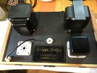
Some basic physical info - it's a big heavy beast! Heavy steel chassis with anodized aluminum front plate. Weighs close to 50lbs, a most of it in the transformers. There are two switches and one mA meter on the front panel and on the back there are input and output banana jacks as well as a big wirewound pot that is connected to the meter. Tubes are an 813 and a OD3.
Let's take a look inside:
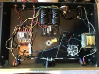
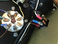
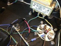
When I got it the wiring was pretty tied down with zip ties and shrink tubing. I've removed them to help figure out the schematic. That said it seems pretty messy in here...
There is a relay in here that is baffling me - it seems to pass the input directly to the output when not energized. When energized it has a weird path through the OPT before it hits the input of the 813 tube.
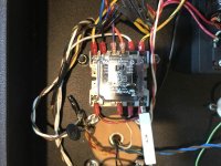
Weirdness abounds in the power supply. The primary taps appear to be connected to the 200V taps and then there is a voltage doubler on the other side.
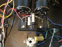
The 7-pin 813 tube socket doesn't appear to have a locating feature - I don't know how you are supposed to know which way to put it in!
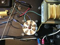
This is the bias pot
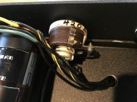
The sketchy jacks
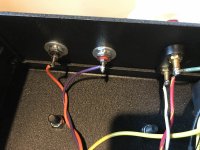
This view is of switch #2 and the unidentified interstage trans
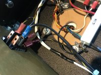
This is switch #1
And this is the filament trans for the 813
I'll post the schem next - limited uploads...
Long time no see, hope you are all doing well!
I wonder if you can help me figure out this mammoth amp a friend of mine picked up at an estate sale? It was a huge sale in Florida full of records and audio equipment, some DIY and others vintage. There were two of these amps, each one sitting on a big speaker. The owner was a famous DJ in Florida and Alabama - I don't know his name. My friend asked me to look at it as he didn't know how to hook it up to his system - no labels anywhere except for the top:

Some basic physical info - it's a big heavy beast! Heavy steel chassis with anodized aluminum front plate. Weighs close to 50lbs, a most of it in the transformers. There are two switches and one mA meter on the front panel and on the back there are input and output banana jacks as well as a big wirewound pot that is connected to the meter. Tubes are an 813 and a OD3.
Let's take a look inside:

When I got it the wiring was pretty tied down with zip ties and shrink tubing. I've removed them to help figure out the schematic. That said it seems pretty messy in here...
There is a relay in here that is baffling me - it seems to pass the input directly to the output when not energized. When energized it has a weird path through the OPT before it hits the input of the 813 tube.

Weirdness abounds in the power supply. The primary taps appear to be connected to the 200V taps and then there is a voltage doubler on the other side.

The 7-pin 813 tube socket doesn't appear to have a locating feature - I don't know how you are supposed to know which way to put it in!

This is the bias pot

The sketchy jacks

This view is of switch #2 and the unidentified interstage trans

This is switch #1

And this is the filament trans for the 813

I'll post the schem next - limited uploads...
Reminds me a little bit of our "ebay friend" of another thread. Maybe when he gets to stage 2 level production...
Lucky find! I never ever ever ever get to see anything like that at an estate sale and if I do, it's for sure taken by the time I get there. I remember one guy actually put the word "Marantz" in his yard sale ad; all gone in the first 15 minutes he told me.
Looking forward to seeing your schematic!
Lucky find! I never ever ever ever get to see anything like that at an estate sale and if I do, it's for sure taken by the time I get there. I remember one guy actually put the word "Marantz" in his yard sale ad; all gone in the first 15 minutes he told me.
Looking forward to seeing your schematic!
The Schematic - With Caveats
So! Here is my first pass at the schematic for the amp:
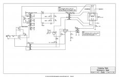
Some notes:
I don't know what the transformers are and I don't want to unsolder anything (right now) to take measurements - even if I knew how!
However, the PT and the OPT appear to be Hammond parts. I think the PT is their 300 series as the dimensions are correct for the X13 size and the wires are all the right colors. You can barely see the residue of the sticker they put on top.
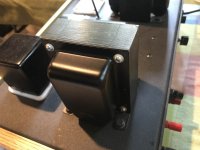
The OPT is probably a Hammond too, a 16xxx SE part but I can't figure out which one. All the wiring colors line up with the exception of one - there is a BLK/YEL where I expected a WHT. I can't see where this may have been spliced in, maybe it was a custom wind? Like the PT, this one has dimensions that line up to their published dims.
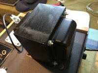
The interstage transformer is an unknown entity. I guessed at it's internal connections. Interestingly it is mounted on a block of white nylon to keep the can isolated from the chassis?
Speaking of interesting mounting - did you see the whole voltage doubler circuit is mounted to a black-painted chunk of wood?!
SO! What does my friend have here?
1. It appears to be a monoblock amp with no gain - you must power it with a preamp. Which he did not purchase.
2. The operating point can be adjusted via the back panel control and you can see that bias point via the meter on the front.
3. You turn on switch #1 first to heat up the 813's filaments
4. Switch #2 turns on the PT and switches the relay, connecting the output terminals to the OPT and also switching the input terminals to..... something...
I haven't got the tubes and I am loathe to fire this up after reading pmillett's dire warnings about the voltages involved in this amp. I have been around plenty of guitar amps and lower powered tube audio but nothing like this!
OK! What are your thought on this thing? Hows the schem look? What is UP with that relay and the OPT?
edit: a more legible schem PDF added...View attachment 813_AMP_schem.pdf
So! Here is my first pass at the schematic for the amp:

Some notes:
I don't know what the transformers are and I don't want to unsolder anything (right now) to take measurements - even if I knew how!
However, the PT and the OPT appear to be Hammond parts. I think the PT is their 300 series as the dimensions are correct for the X13 size and the wires are all the right colors. You can barely see the residue of the sticker they put on top.

The OPT is probably a Hammond too, a 16xxx SE part but I can't figure out which one. All the wiring colors line up with the exception of one - there is a BLK/YEL where I expected a WHT. I can't see where this may have been spliced in, maybe it was a custom wind? Like the PT, this one has dimensions that line up to their published dims.

The interstage transformer is an unknown entity. I guessed at it's internal connections. Interestingly it is mounted on a block of white nylon to keep the can isolated from the chassis?
Speaking of interesting mounting - did you see the whole voltage doubler circuit is mounted to a black-painted chunk of wood?!
SO! What does my friend have here?
1. It appears to be a monoblock amp with no gain - you must power it with a preamp. Which he did not purchase.
2. The operating point can be adjusted via the back panel control and you can see that bias point via the meter on the front.
3. You turn on switch #1 first to heat up the 813's filaments
4. Switch #2 turns on the PT and switches the relay, connecting the output terminals to the OPT and also switching the input terminals to..... something...
I haven't got the tubes and I am loathe to fire this up after reading pmillett's dire warnings about the voltages involved in this amp. I have been around plenty of guitar amps and lower powered tube audio but nothing like this!
OK! What are your thought on this thing? Hows the schem look? What is UP with that relay and the OPT?
edit: a more legible schem PDF added...View attachment 813_AMP_schem.pdf
Last edited:
Maybe the intent was a booster amp, to sit between an existing amplifier and the speaker. In ham radio, this would be called a "linear".
All good fortune,
Chris
All good fortune,
Chris
Looks like your friend was already asking around for info before he bought them. I can find questions on that same amp from december 2020!
The 7-pin 813 tube socket doesn't appear to have a locating feature - I don't know how you are supposed to know which way to put it in!
One hole on the socket is larger than the others and takes a matching pin on the tube.
Actually the 813's two filament pins are fatter then it's others and will only fit into the socket one way.
Looks like your friend was already asking around for info before he bought them. I can find questions on that same amp from december 2020!
Heh, no that wasn't him. That post was from the day of the sale from another potential buyer.
And now I know all about the fat pins on the 813 filament!
I'm not sure about the use of this amp though. It makes me wonder why someone would build something like this? There must be $500 in iron in the pair of them! The fact that the input terminals connect directly to the output when the amp is turned off does lend credence to the "booster amp" theory. Can someone elaborate on that concept - I've never heard of that before.
well they were used to Drive Klipsch Cornwalls which are a smidge over 100dB/w depending on the frequency you chose to measure at 🙂. So a coupla watt total overkill SET amp would seem to be perfect to go with them?
A decent line stage would probably drive those speakers to acceptable levels for late night listening.
A decent line stage would probably drive those speakers to acceptable levels for late night listening.
Perhaps an easy way to A/B? I'm surprised they didnt think of a remote -
"Here's how the music sounds normally. Now, I'm going to switch on the Orlen super magic musicifier power signal processors. Once the filament is warmed up, I can quickly go back 'n forth with these, so you can easily hear what they do!"
"Here's how the music sounds normally. Now, I'm going to switch on the Orlen super magic musicifier power signal processors. Once the filament is warmed up, I can quickly go back 'n forth with these, so you can easily hear what they do!"
"Boosters" are/were common in amateur radio transmitters. Build your first Xmitter at a few Watts to save money and trouble and to limit your annoyance range. When your pocketbook recovers get a 813 to take your few-Watts up to many-Watts. This was also very popular on CB radio bands which were limited by regulation to 5 Watts; 11 meter ham radio "linears" (would pass AM/SSB modulation) existed up to half a kiloWatt nominal output. Called "foot-warmers" because CB-ers kept them out of sight under the desk.
You occasionally see the idea in 1947 audio books but it has never been common. Even here, more in ham radio than hi-fi or PA.
If you did not get the little 2A3/300B amp this was made for, scrap the transformer and the switching, start afresh as a 813 plus appropriate driver.
You occasionally see the idea in 1947 audio books but it has never been common. Even here, more in ham radio than hi-fi or PA.
If you did not get the little 2A3/300B amp this was made for, scrap the transformer and the switching, start afresh as a 813 plus appropriate driver.
Last edited:
Do you happen to know the turns ratio of the input transformer?
The 813 is fairly easy to drive. You may get decent power from a low impedance source with the right input transformer.
The 813 is fairly easy to drive. You may get decent power from a low impedance source with the right input transformer.
Thanks for the excellent explanation PRR! I totally get the HAM mindset - but I don't know why someone would do this for an audio application. Maybe he had a HAM background too?
I do not know the rations of the transformer as I was trying to avoid desoldering anything. Looking at it I could probably figure it out pretty easily though. The process is insert 1VAC into one pair and measure the others?
PRR's suggestion of gutting it and building a new circuit inside is compelling. I don't have the chops to design such a circuit though and, aside from pmillett's SE amp I haven't found any other 813 audio builds in my googling. I'm also a more than little scared of the voltage involved to get the tube into a good place. Seems like 500V is the starting point based on the datasheet's curves and that is at the top of my experience!
- Home
- Amplifiers
- Tubes / Valves
- Estate Sale Mystery 813 Amp - How Can This Work?