Finding more issues and this is just on the right channel board, haven't gone to the left channel yet. Found a few IN4148 diodes either shorted or physically broken so I replaced all of them to be on the safe side. There must have been quite the short to take all those out. Next will be checking the larger transistors, resistors, checking continuity and touch soldering the connections. The journey continues!
Like
Like
Progress Report
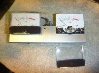
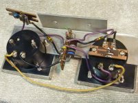
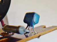
The amp plays well especially after replacing all the MJ410 power output transistors with MJ15024 as recommended by a member. The meter bulbs still light faintly. Removed the meter assembly and checked the !N4004 diode, 680 resister and two 150k's, they all are at spec. Then touch soldered the back of the meter boards in case there were any cold solder joints. On each board there is a 3k resistor and something that looks like a rectifier or transistor that has no markings on it and am not sure what job it does. Would appreciated any info on what this component is and how to measure it. The reason I'm asking is that I fear I may have damaged it as the meters peg a hard right upon powering on remaining in that position until powering off, which it didn't do before. Seems like there's too much voltage causing this perhaps from the bridge rectifier. I measured at the rectifier's + and - and found 151vdc, the schematic shows there should be 100v. Is a new rectifier in order or could it be the mysterious part behind the meter boards? Thanks for your input!
The amp plays well especially after replacing all the MJ410 power output transistors with MJ15024 as recommended by a member. The meter bulbs still light faintly. Removed the meter assembly and checked the !N4004 diode, 680 resister and two 150k's, they all are at spec. Then touch soldered the back of the meter boards in case there were any cold solder joints. On each board there is a 3k resistor and something that looks like a rectifier or transistor that has no markings on it and am not sure what job it does. Would appreciated any info on what this component is and how to measure it. The reason I'm asking is that I fear I may have damaged it as the meters peg a hard right upon powering on remaining in that position until powering off, which it didn't do before. Seems like there's too much voltage causing this perhaps from the bridge rectifier. I measured at the rectifier's + and - and found 151vdc, the schematic shows there should be 100v. Is a new rectifier in order or could it be the mysterious part behind the meter boards? Thanks for your input!