Though I posted this thread in the Pass Labs forum, I thought this may get better attention here and seemed more appropriate.
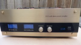
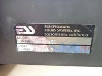
I recently acquired this power amp with an unknown history but learned through a member on the Audiokarma forum that I might find info on this site. The amp claims 500 watts or 250 per channel, weighs considerably and appears very well built. After cleaning up the exterior I opened it up and found the transformer was loose and some small black plastic pieces were on the bottom of the chassis along with some small but long machine screws. Removed the screws, vacuumed up all the plastic bits, tightened down the bolts securing the transformer, traced those screws to the back of the output meters, sprayed the pots with Deoxit then visually inspected the circuitry for any abnormalities with all appearing fine. Another thing, those heat sinks extend way out and have sharp edges, I've the scratch marks on my arms to prove it!
Powering it up using a DBT with a 100 watt bulb and 8 ohm dummy load per channel with gain pots set at a minimum, the bulb was first bright then momentarily darkened then came back on at about 3/4 the original brightness. there was no Magic Smoke or explosions! That's about all I had time for today but it looks like a promising project.
Found some info on the bias and offset from a restorer online who thought it should be set to 100mv but this applied to the model 200, haven't found much info on the model 400. Do you think the 100 watt bulb is insufficient for testing this powerful amp or should it be a greater wattage? The transformer is massive and rated at 1.5 killowatts, pretty intimidating and approached with caution! I've some info on this and will have to read it carefully before proceeding further but so far don't see any info on how to go about setting the bias or offset, any info regarding doing this would be most appreciated!
Attachments
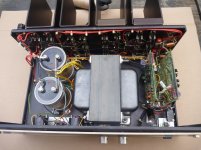
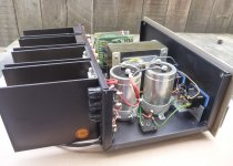
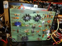
Nice looking amp - it's very clean inside. That is an impressively sized transformer and main caps. Looks like you found yourself a nice piece of vintage hardware. How does it sound?
Can you make photos straight from the back to see how many and which power transistors are used. another one of the circuit board to identify the adj. pots.
The bulb seems to indicate it is working, It will be lit by the magnetizing current already which flows additional to the load current, so try a higher wattage
The bias depends on the number of paralleled power transistors, seems there are 4. Probably around 120-200mA. Difficult to say without the type numbers
Measurements are needed, the voltage across the big caps, the offset voltages at the outputs and can it be adjusted
Nice looking amp - it's very clean inside. That is an impressively sized transformer and main caps. Looks like you found yourself a nice piece of vintage hardware. How does it sound?
It was an eBay purchase with the seller parting with it for $100 plus shipping. The faceplate was bent on the lower left corner which I bent back as best I could. Considering how much this thing weighs and how bulky it is, it's no wonder someone dropped it. Other than that, it's in great shape cosmetically for an amp of this vintage. It works and does sound good but am cautious about driving any speakers with it too loudly until I know how to get the bias adjusted properly. I had it hooked up to a pair of bookshelf speakers and noticed how hot the amp became just at a low volume. Using a infrared thermometer, I saw 117 degrees F on the right channel heat sinks with 109 on the left after operating the amp an hour. That's when I shut it down until I obtain more info on the amp's proper setup.
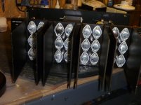
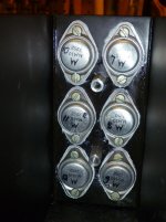
There are 24 Motorola MJ410 power output transistors, 12 per channel. The left channel output voltage measured at 115 mvdc, the right was a bit higher at 130 mvdc and adjusted by the single turn 5k pots on each board while hooked up to a DBT with no load on the inputs or outputs, gain controls set to minimum. One MJ410 was found to be shorted on the left & right channels and replaced with NTE94 which I happened to have and appears to have the same characteristics as the originals. This had no effect on the output voltages which remained the same. I'm considering removing and testing the small MPSL01 NPN signal transistors, suspecting there might be issues there and also replacing the 4.7uf 63v tantalums with WIMA equivalent rated ones. Any thoughts on doing this would be appreciated.
Last edited:
The faceplate was bent on the lower left corner which I bent back as best I could. Considering how much this thing weighs and how bulky it is, it's no wonder someone dropped it.
Be careful with cheap couriers.
I sent two heavy amps out by a cheap one and the blighter dropped both and bent them.
Yes, how true. I received a pair of Fisher ST-550 speakers in less than pristine condition than were originally shipped. Spent several days repairing the crushed corners and grain matching the veneer to get it looking decent.
On the ESS faceplate, I had to carefully bend it back to shape in a vise with protective plates so as not to mar the finish then finished flattening it out using a hammer to finally getting it to look right, not perfect but acceptable. 🙁
On the ESS faceplate, I had to carefully bend it back to shape in a vise with protective plates so as not to mar the finish then finished flattening it out using a hammer to finally getting it to look right, not perfect but acceptable. 🙁

There are 24 Motorola MJ410 power output transistors, 12 per channel. The left channel output voltage measured at 115 mvdc, the right was a bit higher at 130 mvdc and adjusted by the single turn 5k pots on each board while hooked up to a DBT with no load on the inputs or outputs, gain controls set to minimum. One MJ410 was found to be shorted on the left & right channels and replaced with NTE94 which I happened to have and appears to have the same characteristics as the originals. This had no effect on the output voltages which remained the same. I'm considering removing and testing the small MPSL01 NPN signal transistors, suspecting there might be issues there and also replacing the 4.7uf 63v tantalums with WIMA equivalent rated ones. Any thoughts on doing this would be appreciated.
R8 is what you trim to minimize offset. What you’ve got is probably within spec but I normally like to see less. Unfortunately if you do trim it, you need to do so at full voltage (not on a DBT) as the value that gives the lowest offset will vary with supply voltage. What you’re not on a DBT, you may get less offset than you’re seeing now.
You shouldn’t replace just *one* shorted output transistor in any bank. What you end up replacing it with may be different enough where they don’t share properly anymore - especially considering the age of the originals (see date code). If there is one and only one bad one in a batch, put the new one in the driver position, and put all originals in the 5 output positions. Safest thing to do is replace all, but that’s about $40 per bank so it’s understandable why you would hesitate. Mj410s were probably the only thing available that would do the voltage back in 72. Better choice today is MJ15024. If you do replace a bank, replace all in any given bank with these. And only new ON Semi devices or verified old stock Motorola. If I was going to be beating on this amp I would use these. For gentle home use with 8 ohm speakers, the originals are fine. Once you move the “odd” transistor to the driver position to keep all outputs original. There is quite a bit of difference between a transistor made in 72 and one made more recently - even if it is the same type number.
I would ditch the tantalum coupling caps, but probably replace them with good quality bipolar electrolytics. Nichicon, Chemicon, Panasonic. No need to go more expensive. And you can ditch the parallel 1N4148s - they are there to keep the tantalums from bursting into flames if there is any reverse voltage. I would just trip out the boot strap cap too while I’m at it. Just regular high quality electrolytic.
There is quite a bit of difference between a transistor made in 72 and one made more recently - even if it is the same type number.
I got caught out with sold for spares Maplin disco amplifier 225WRMS.
It came with no outputs so I bought in new transistors.
The new ones oscillated nicely.
Had to increase VAS capacitor a little to tame it.
If you have 12 transistors per bank and cant get matched replacement just run it without that transistor, if your not going to hammer the amp.
R8 is what you trim to minimize offset. What you’ve got is probably within spec but I normally like to see less. Unfortunately if you do trim it, you need to do so at full voltage (not on a DBT) as the value that gives the lowest offset will vary with supply voltage. What you’re not on a DBT, you may get less offset than you’re seeing now.
You shouldn’t replace just *one* shorted output transistor in any bank. What you end up replacing it with may be different enough where they don’t share properly anymore - especially considering the age of the originals (see date code). If there is one and only one bad one in a batch, put the new one in the driver position, and put all originals in the 5 output positions. Safest thing to do is replace all, but that’s about $40 per bank so it’s understandable why you would hesitate. Mj410s were probably the only thing available that would do the voltage back in 72. Better choice today is MJ15024. If you do replace a bank, replace all in any given bank with these. And only new ON Semi devices or verified old stock Motorola. If I was going to be beating on this amp I would use these. For gentle home use with 8 ohm speakers, the originals are fine. Once you move the “odd” transistor to the driver position to keep all outputs original. There is quite a bit of difference between a transistor made in 72 and one made more recently - even if it is the same type number.
I would ditch the tantalum coupling caps, but probably replace them with good quality bipolar electrolytics. Nichicon, Chemicon, Panasonic. No need to go more expensive. And you can ditch the parallel 1N4148s - they are there to keep the tantalums from bursting into flames if there is any reverse voltage. I would just trip out the boot strap cap too while I’m at it. Just regular high quality electrolytic.
Thank you for this valuable info. I'll check into MJ15024's and see if it's financially feasible now. I like the idea of replacing the tantalums with a quality electrolytic but what and where is the 'boot strap' cap?
Q10 shown as an NPN must be PNP
like the amplifier a poor mans phase linear
regards Trev
like the amplifier a poor mans phase linear
regards Trev
Last edited:
Thank you for this valuable info. I'll check into MJ15024's and see if it's financially feasible now. I like the idea of replacing the tantalums with a quality electrolytic but what and where is the 'boot strap' cap?
C9 is the boot strap cap. If it gets leaky the amp can get ‘flaky’. Tantalum caps are just bad news in general. At one time they were “better” than electrolytics. Not anymore by a long shot.
15024’s are about $7 apiece these days.
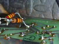
As I was touch soldering on the right channel circuit board I found this trace that was unintentionally soldered to the next one by the previous owner. This might be one of the reasons the amp is not up to snuff and not functioning correctly. I'm going to carefully scrutinize every part and connection against the schematic to see if there's more surprises waiting to be discovered. Thank goodness for my DBT! I knew there would be issues down the line when I received it with the transformer being loosely mounted to the chassis along with small machine screws lying about that belonged to the back of one of the meters and a mashed transistor near the transformer.
Attachments
Last edited:
Just be very careful and methodical. It isn’t too hard to get amps like this up and running - and it’s always a joy to do so. As far as the bias is concerned - thus type of amp is often operated at zero bias in the outputs. The Phase Linears and Crowns of the day were supposed to be. The setting on those old amps is 0.35 volts across the output stage emitter resistor. The drivers are operated at high bias, about 60 mA - set by the 10 ohm Rbe for the output stage. The sound can improve a bit by running a few mA of bias per output transistor, if the resulting bias doesn’t cause oscillation. With some output transistor types this can happen. The old RCA hometaxial types didn’t like to be run “just barely cracked open - you either run at zero bias or cranked it way up to keep it stable. Running it up at 20 or 30 mA per output device is too high for any of these amps at this supply voltage. Heat sinks just aren’t big enough. When I rebuild this type of amp I run at 3mA per output transistor. The MJ410’s should do this, and the 15024’s certainly will.
True, it does look like a poor mans Phase Linear. Output stage is exactly the same - which is why I had the suggestions for bias above. The PLs are more prone to oscillation because they have more gain in the front end and a higher feedback factor. The originals have two cascaded differential stages, the Series Two had those stages replaced by an op amp. Yours just has a regular Lin front end which is straightforward to stabilize and usually pretty foolproof.
Q10 shown as an NPN must be PNP
like the amplifier a poor mans phase linear
regards Trev
True, it does look like a poor mans Phase Linear. Output stage is exactly the same - which is why I had the suggestions for bias above. The PLs are more prone to oscillation because they have more gain in the front end and a higher feedback factor. The originals have two cascaded differential stages, the Series Two had those stages replaced by an op amp. Yours just has a regular Lin front end which is straightforward to stabilize and usually pretty foolproof.
Last edited:
Thank you for your input and expertise wg_ski on this amp. There's not much info on the ESS and I've yet to hear back from Rick at ESS Labs so every bit I can gather from the experts here is most appreciated.
As I was removing and testing board components on the right channel I found all three of the MPSL01 transistors shorted as tested on my Peak DCA55. I'll be testing the diodes and other components out of circuit to see if anything else is amiss.
Again, thank you for your help!
As I was removing and testing board components on the right channel I found all three of the MPSL01 transistors shorted as tested on my Peak DCA55. I'll be testing the diodes and other components out of circuit to see if anything else is amiss.
Again, thank you for your help!
- Home
- Amplifiers
- Solid State
- ESS Model 400 / 500 Watt Power Amp