A couple months ago I acquired two 1a AMT heil's from a guy who's cabinets have been ruined in a move. This last week I found some 1d cabinets still in the box. Appear to have never been used. The guy have acquired them from the estate of a hoarder and was parting them out. I got the cabinets and The 1d crossovers. I then called up the guy I got the Heil's from and got his woofers and passive radiators. So I have everything to put these back together.
My problem is the guy partying up the speakers had already removed the 1D crossovers from the cabinets. So I'm not quite sure how to hook everything up.
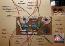
The attached image show the crossover and is labeled with what I think I know.
Can any one help me with the proper wiring, positive, neg, mid pres, & brilliance
My problem is the guy partying up the speakers had already removed the 1D crossovers from the cabinets. So I'm not quite sure how to hook everything up.
The attached image show the crossover and is labeled with what I think I know.
Can any one help me with the proper wiring, positive, neg, mid pres, & brilliance
Attachments
Physical layout sketch
I took the time this week to sketch the physical lay out of the crossover. By doing this I was able to determine the positive negative going to the woofer and tweeter. I'm still unsure of how to hook up the two potentiometers. In the attached PDF you'll see I indicated which wires were cut when it was removed from the speaker. Being a mechanical guy not electrical guy is about as far as I can take this. Obviously this doesn't look like a regular circuit diagram because this is the physical connections on the crossover. So if you compare this to the image in my previous post it should have everything that's needed. I'm hoping someone out there and figure this out.
I took the time this week to sketch the physical lay out of the crossover. By doing this I was able to determine the positive negative going to the woofer and tweeter. I'm still unsure of how to hook up the two potentiometers. In the attached PDF you'll see I indicated which wires were cut when it was removed from the speaker. Being a mechanical guy not electrical guy is about as far as I can take this. Obviously this doesn't look like a regular circuit diagram because this is the physical connections on the crossover. So if you compare this to the image in my previous post it should have everything that's needed. I'm hoping someone out there and figure this out.
Attachments

- Status
- Not open for further replies.