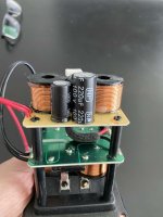
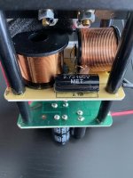
Having just replaced cheap Intertechnik capacitors (some of them NPE) to mostly ClarityCap CSA in an Audio Physic Tempo V crossover, I find that I enjoy the much greater fidelity but it's unbalanced.
I'm nervous that now that I've gone and changed the ESR, even capacitorwise, the quantitative issue that comes with resistance changes is equally major to the qualitative difference that is heard with better parts quality. How I see it, a way to try and keep the original tonal balance when upgrading from old/cheap parts would be to replace all parts such that the ratio of their ESRs is about the same. Does this make sense, as in, could it be so linear as this? (I know just a little bit of resistance not being linear)
I'll be replacing the coils next (waiting for an LCR meter), they are of differing gauges and to my eye, all of them too wimpy. Since ESR would be even more major with inductors, care should be taken, maybe a good matching will correct the unbalancing act that came about with only replacing the caps?
Now, since I want lower resistance for all coils, I had this plan: the biggest coil, a 1st order for the bass, would be a Jantzen C-Coil with 0.07ohms, a reference for the ratio. If the original second-largest coil which is series in the mid-circuit had, say, twice the resistance of that largest one, I'd ideally strive for a ribbon coil with around 0.14ohms (too expensive), but maybe just down to over 0.2ohms would be sensible with a normal air core. Just hypothetically.
This was a very long-winded way of asking, when upgrading an old crossover, if I decrease the ESRs of the crossover's components in a proportional ratio, would I most likely end up with more balanced results, assuming the original design sounds balanced?
You'd probably change more than that, as they interact with the varying impedances of their loads, and the circuits are different. Why don't you find out where by simulating?
Do I get anywhere with any software until I have acquired tools to measure the drivers?Why don't you find out where by simulating?
I'll be getting the tools, but my patience allows me to spend on them only after I've spent to replace every stock part in the crossovers first. So will have to go a bit blind and then probably correct later, but here I'm wondering how far this matter of ESR ratios could be intuitively generalized / "somewhat predicted".
Have I understood correctly that inductor ESR can be tuned with resistors afterwards, but for capacitors not so much? Of course I'd rather avoid adding resistors... The goal is to have a crossover with as little loss as possible, while not whacking the tonal balance between the drivers out of sync.
Last edited:
Yes, you can learn where and how much each change affects you. If you can measure impedances and use the actual crossover values. To some degree it may work with factory impedances.
How do you mean by that?How I see it, a way to try and keep the original tonal balance when upgrading from old/cheap parts would be to replace all parts such that the ratio of their ESRs is about the same.
It is improbable to substitute for same ESR capacitors ratio of different capacities. Can you simulate and measure capacitors' ESR?
I'm considering upgrading caps to a crossover, but I fear lower ESR from the new better capacitors of the same values might unbalace the speaker drivers, despite a posible sound quality gain, as it did to you.
I'd have this done by a professional, but the choice is mine. Hence the dilemma...
Can it be solved by adding or increasing a resistor for the tweeter?


Last edited by a moderator:
If the values of the capacitors are the same, the only difference that the Clarity Caps will bring is a much tighter value tolerance of 3%.....Along with reduced ESR....Maybe you have now revealed a different "flaw"...or most likely you have been used to the previous "balanced" sound which is actually "unbalanced" & you have to get used to the way the speakers now sound...
This is AC theory.
Not DC theory.
Being AC, the 'resistance' through a capacitor (and inductor) will change with the frequency at which it is tested.
Thus we have, impedance. Which is a variable, frequency dependant, resistance.
Not DC theory.
Being AC, the 'resistance' through a capacitor (and inductor) will change with the frequency at which it is tested.
Thus we have, impedance. Which is a variable, frequency dependant, resistance.
Measure the old caps, measure the new caps, and maybe add a resistor to substitute for the missing esr. You'll need access to at least a oscilloscope and a audio freq oscillator - or an impedance bridge. Basic EE stuff. Actually, these cheap Chinese bridges are pretty darn good for the money: https://www.aliexpress.us/item/3256...22b3793mVv2CW&algo_pvid=a7bd2458-602d-46c2-ae
The first thought that comes to mind is that it simply got louder due to less resistance...?"much greater fidelity but it's unbalanced" - seems like a contradiction???
Indeed. Strictly speaking, resistance is not frequency dependent.. however capacitor measurements sometimes show variations in the 'equivalent' series resistance, belying it's unique origin.This is AC theory.
Not DC theory.
Allen, Could you expand on that, or provide a link for further reading ?
The only time I worry about the caps esr is when their obviously faulty (very high esr or leaking).
Even then all i do is swap in a PP if it fits physically.
Actually have a pair of immaculate vintage tannoy crossovers here to rebuild/repair now.
The only time I worry about the caps esr is when their obviously faulty (very high esr or leaking).
Even then all i do is swap in a PP if it fits physically.
Actually have a pair of immaculate vintage tannoy crossovers here to rebuild/repair now.
Perhaps this will give an outline of the problem - https://www.diyaudio.com/community/threads/new-project-esr-tester.378451/post-6822265
I also know there have been some in depth studies done here in the past.
I also know there have been some in depth studies done here in the past.
When comparing electrolytic and film capacitors of the same capacitance, several factors come into play, especially regarding the quality and equivalent series resistance (ESR) of electrolytic types. Testing reveals minimal variations in sound pressure levels, with differences peaking around 0.2 dB. Specifically, under the least favorable conditions, the differences are about +0.7 dB from 1 to 2.5 kHz and -0.2 dB from 2.5 kHz to 9 kHz.
While these differences are more pronounced than those between standard and premium film capacitors, they remain relatively insignificant in practical applications. It's worth noting that there's no evidence to suggest that the average person can hear differences in ESR—unless you possess superhuman hearing!
For high-quality electrolytic capacitors, longevity typically isn't a major concern. The primary issues involve their tolerance values and the potential for capacitance drift over time, which can be problematic in tweeter crossovers. As such, it's generally advisable to avoid using them in these applications.
Importantly, measurements indicate that film capacitors do not automatically provide better sound quality in crossover applications compared to electrolytic capacitors. Replacing electrolytic capacitors with film options in a crossover circuit without verifying their values with an LCR meter may lead to changes in sound. However, it's crucial to understand that about 99% of any perceived differences likely stem from variations in capacitance (20% vs. 2%) due to tolerance rather than any inherent superiority of film or premium capacitors.
Ultimately, the most important factor is the overall design of the crossover and the interaction of all its components.
While I agree with all that you say, when equalising ESR and capacitance between electrolytic and film by adding resistors in series, film may still sound better for better quality. 20% capacitance variance is too high. It goes around 2%-5% for film and electrolytic if I'm not mistaken.
Last edited:
All the newer speakers (Polk Audio, KEF, Denon, Wharfedale etc.) made in China have SPT/Topmayelectronic bipolar capacitors with a tolerance of 20%. That’s something you should immediately take and throw in the trash.
And use something like this
https://www.hificollective.co.uk/article/bipolar-electrolytic-capacitors-for-crossovers.html
And use something like this
https://www.hificollective.co.uk/article/bipolar-electrolytic-capacitors-for-crossovers.html
- Home
- Design & Build
- Parts
- ESR ratio in crossover upgrade