I found a PCB layout by r!sc! for ESP P3A in this forum.
http://www.diyaudio.com/forums/showthread.php?postid=735227#post735227
Thanks a lot for the posting.
I built some chip amps and they work good.
And this is my first try of solid state amp DIY.
I'm doing with universal PCBs.
I made 1 channel and tested with +12V, -12V rails.
- Output offset DC is about 50mV.
- Both MJ15024 and 15025 are just a little warm.
- I set the bias current around 75mA(by setting the voltage
drop across the two 0.33 ohm resistors is about 50mV).
- +V and -V are about +15V and -15V
- Sounds good. 🙂
No problem until now with that channel.
I made one more channel and have some problems.
- Output offset DC is about -3.4V.
- MJ15024 is getting hot in a few minutes. But 15025 is cold.
- I cannot set the voltage drop across the two 0.33 ohm resistors
below 240mV with the VR.
- +V and -V are about +15V and -14V
- Sounds not bad. No hum.
I checked over and over and rechecked.
And I cannot find any problems like short circuits, open circuits.
Could you please give me some ideas or locate the point
for solving this problems?
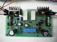
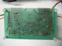
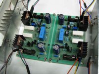
Pics-Channel with problems(2/2)
This is the channel with problems I mentioned(2/2).
I made this channel with the mirrored layout.
So, you can see the change of direction with BC546s and BD140.
Instead of changing directions, I changed some wiring paths for
MJE15032, MJE15033.
This is the channel with problems I mentioned(2/2).
I made this channel with the mirrored layout.
So, you can see the change of direction with BC546s and BD140.
Instead of changing directions, I changed some wiring paths for
MJE15032, MJE15033.
Attachments
PA
Hello
A good design is the Nashville NA 2200 power amp. It´s work with a +20/-20 V to +65/-65 V. In the past, I built the ESP amp but it´s don´t work.
Sandro
Hello
A good design is the Nashville NA 2200 power amp. It´s work with a +20/-20 V to +65/-65 V. In the past, I built the ESP amp but it´s don´t work.
Sandro
It works just fine when built correctly.
The non-working amplifier is probably oscillating. You need to keep the wires to the output transistors as short as you can. The P3A uses a CFP output stage which will oscillate if not used carefully.
Why did you mirror the layout ? Isn't it possible that you have made an error when doing this ? Why not build your second channel as an exact copy of the working one ?
If a pcb is mirrored, then the 3 lead devices called transistors will have to be corrected while assembling
or u will have to buy the mirror copy of the transistor LOL!!!
Gajanan phadte
or u will have to buy the mirror copy of the transistor LOL!!!
Gajanan phadte
I solved the problems.
After inspecting the voltages of all the points
and changing the parts one by one, I found that
Q1(bc546a) has some problem.
By changing Q1, all the problems had gone.
So, I think that mirroring the layout gives no problem.
Output Offset V = about 10mV
Bias Current = set around 70mA
I'm testing and enjoying the 2 channels now.
Thank you so much.
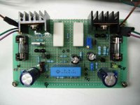
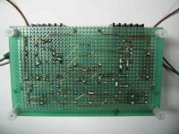
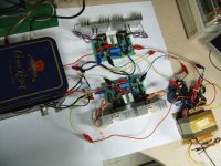
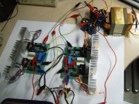
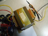
Testing and some pics(1/3)
With Recycled Transformer, I got +/-24V.
So, I could give more than +/-30V to my P3A.
- Output Offset DC : about 25mV for each channel
- Bias Current : set again down to about 75mV
- Heatsinks : just a little warm
- Sounds smooth and easy, rich bass
- No hum
Everything is great until now.
With Recycled Transformer, I got +/-24V.
So, I could give more than +/-30V to my P3A.
- Output Offset DC : about 25mV for each channel
- Bias Current : set again down to about 75mV
- Heatsinks : just a little warm
- Sounds smooth and easy, rich bass
- No hum
Everything is great until now.
Attachments
Cool 🙂 But you should shorten the wires to the output transistors... the longer they are, the more potential for the amplifier to oscillate.
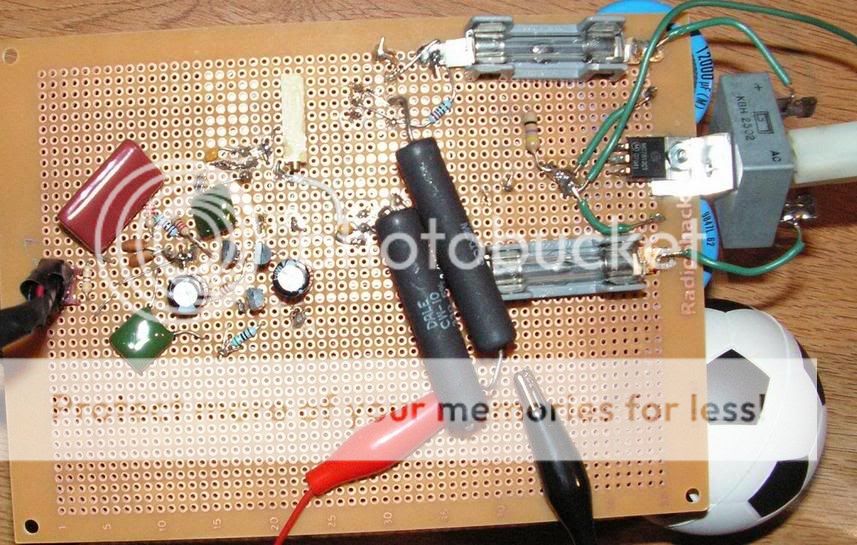
Heh, that's a great amp; I built one of my own layout on a perfboard just for fun. It works great; I can't hear any hum at all even with my ear stuck on the speaker, and it sounds great - I'm sure the oversized caps helped (gotta use what you have!)
It looks messy, but it's better to keep the signal paths short and isolated from power when possible. Here are a couple of crappy pics...
Top of board (old CPU HSF)
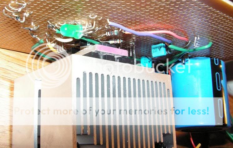
Bottom (I guess?) of board:
It looks messy, but it's better to keep the signal paths short and isolated from power when possible. Here are a couple of crappy pics...
Top of board (old CPU HSF)
Bottom (I guess?) of board:
Shortening the wires...
Thanks jaycee and j.videtich.
I'm looking for some adequate chassis for this amp.
Arranging the parts in the chassis, I'll shorten the wires.
Anyway, you have awesome skill j.videtich.
I think I cannot do that like you.
Thanks jaycee and j.videtich.
I'm looking for some adequate chassis for this amp.
Arranging the parts in the chassis, I'll shorten the wires.
Anyway, you have awesome skill j.videtich.
I think I cannot do that like you.
Have you felt the heatsinks for your P3A when it's under heavy load? Rod recommends a MUCH bigger heatsink that that, IIRC, and I'd recommend it also. If the slightest thing goes wrong, I'd worry about burning out the chips with such small sinks 🙁
Heatsink
Thank you for your recommendation, sorenj07.
I'm still testing my P3A.
I didn't try the max. vol. or so.
Because, I got really heavy sound with just
about 11 o'clock position of my pot.
With easy listening vol., position, the heatsinks are
just a little warm after several hours or playing.
But, as you said, I'll get more large heatsink later on.
Hi,
if I read correctly you are running 1pair of MJ15003/4 from +-30Vdc supply rails.
At this voltage small heatsinks are OK.
If you run 4ohm speakers you may require bigger sinks, particularly if you like to party or if the weather is very warm.
If the weather is very warm AND you are partying AND you run 4ohm speakers then you WILL NEED BIG sinks.
Did Soren say chips? Where?
The collector lead to the MJ15003/4 can go to the bolt fixing on the near side of the sink. AVOID the extra length to take it to the far side.
Can you isolate the sinks from earth? Then the output devices can be bolted direct to sink with thermal compound to keep them cooler. Much cooler than using mica or thermal pads.
my p3a
hi,
i 've finished my p3a,
the pcb is similar to the layout mentioned in previous posting.
transistor bc546, bd139/140/. sc5200/1943
nohicon gold tune for elctrolytic, Wima and evoc Poly caps
DC supply +/-30 VDC
bias 75mA to 200mA
DC offset 12 mV and 7.8mV
imo, my p3a amplifier sounds bad.
it remind me of early 70's cheap transistor amplifier's sound
ie,.shrill treble, recessed midrange, weak bass. flat image.
I've changed the input transstor BC546 ( to 2n5551 and then sc2240) driver transistor bd139/140) to MJE 15030/31, SA1837/ SC4793. to no avail.
I'll tinker with the i/p and driver biasing, hopefully it'll help.
any suggestion for improving the amplifier?
rgds,
- Status
- Not open for further replies.
- Home
- Amplifiers
- Solid State
- ESP P3A problems