Anyone know what is the purpose of C2 at the inverting input of the opamp in this schematic ? C6 is to filter RF frequencies ?

Last edited:
In the same schematic above, what does R2 do ? The opamp part of the circuit looks like Cmoy headphone amplifier. But in the Cmoy amp R2 resistor at the opamp input is not there. What does R2 do ?
R2 and C6 form a low pass filter to prevent RFI from causing amp noise or oscillations.
C2 is the feedback ground shunt AC decoupling cap. It can be omitted but helps to prevent having a DC offset at output.
Gain is set by (R3+R4)/R3.
C2 is the feedback ground shunt AC decoupling cap. It can be omitted but helps to prevent having a DC offset at output.
Gain is set by (R3+R4)/R3.
I built the Headphone amp on a breadboard. Built with minimal parts from original schematic. I left out alot of capacitors. This is the schematic of what I built on the breadboard.

Added output capacitors as the DC offset was 30mv per channel. Used NE5532 opamp. Listening to it now and amazed that it even works on the breadboard ! It is silent with nothing playing. From initial listening, I can say that it sounds good. Need to listen more before I can describe its sound.

Added output capacitors as the DC offset was 30mv per channel. Used NE5532 opamp. Listening to it now and amazed that it even works on the breadboard ! It is silent with nothing playing. From initial listening, I can say that it sounds good. Need to listen more before I can describe its sound.
hi, congrats,
i recommend to get the pcb from xrk and build it properly before you come to conclusion.
ESP HPA is a sensitive design as warned by Mr. Elliott himself, pl build it properly and then share your experience.
prasi
i recommend to get the pcb from xrk and build it properly before you come to conclusion.
ESP HPA is a sensitive design as warned by Mr. Elliott himself, pl build it properly and then share your experience.
prasi
I do not even have the RF filter and decoupling cap for the opamp. It still works ( guess I got lucky). I have seen previous posts here claiming that opamp can oscillate. How would I know if mine is oscillating ? Do I hear that as some sort of distortion ?
Been listening to this amp and comparing with Hugh's Class A headphone amp. Both the amps are good but they sound slightly different. Hugh's Class A amp has really clear vocals. The vocals are much smoother and sweeter on Hugh's class A amp than the esp HPA.
The esp HPA seems to have slightly better separation in instruments. This amp also has a slightly bigger soundstage. Like when I was listening to Twenty one pilots - Chlorine, the drum playing on the left at the start of the song seems further. The drums feel more realistic with Hugh's Class A amp though. Now I can't tell which amp is better. They are both different. Some songs sound better on esp HPA and some better on Hugh's Class A amp.
The esp HPA seems to have slightly better separation in instruments. This amp also has a slightly bigger soundstage. Like when I was listening to Twenty one pilots - Chlorine, the drum playing on the left at the start of the song seems further. The drums feel more realistic with Hugh's Class A amp though. Now I can't tell which amp is better. They are both different. Some songs sound better on esp HPA and some better on Hugh's Class A amp.
Which of Hugh’s Class A amps? There are many.
Sry I did not specify, this is what I built (schematic in post 1134) Aspen Headphone Amp
I used BD140 and BC550 transistors in my build.
I was trying to build the Pocket class A amp designed by you but matching the Jfet was such a pain that I gave up for the time being.
I have a 1000uF output coupling capacitor for the esp HPA to protect against DC. When I used 0.1uF film bypass capacitor on the 1000uF output cap the soundstage seems slightly larger and the guitar strings in some songs feels more real. It feels like the strings have longer decay. I am not sure if I am imagining it. Can using bypass capacitor have such an effect ? The headphones I use are 32ohm.
Matching FETs is not critical, just pick two consecutive FETs from a tape roll. Regarding Hugh’s amp - that is his most basic one. He has better ones including my pocket Class A (PCA). Performance of my PCA easily beats the BD140 based one, and probably the ESP if using higher impedance headphones. The BF862 JFET is perhaps one of the best input stage devices - ultra low noise and very linear and sensitive. The output is a MOSFET so has lower impedance than the BJT for deeper and more powerful bass.
For 32ohm headphones, use 2200uF caps. Bypass film caps are a good idea and even 2.2uF ones like MKS are good. With PCA, if phones are very sensitive (100dB+) it can work, else might cause higher distortion.
For 32ohm headphones, use 2200uF caps. Bypass film caps are a good idea and even 2.2uF ones like MKS are good. With PCA, if phones are very sensitive (100dB+) it can work, else might cause higher distortion.
Last edited:
I bypassed the 1000uF output cap with 0.1uF film cap. So bypass cap need to be of higher value to have more effect ?
It’s a subjective area - value and type of bypass cap can change perception of sound quality.
Try metal foil in oil for example. Larger value will have impact down to mid range etc. smaller vale for treble etc. silver will be brighter, paper will have a warmer sound.
A very good bypass is a cheap silk electrolytic - Elna Silmic II 10uF 35v ($0.35 ea) does wonders to the sound quality if you like a smooth sound with clear vocals.
It’s an area of user adjustable tweaking and listening fun. Try DC coupling (no caps) to listen to “baseline” case. Compare to that. If you build actual PCB circuit, it is pretty safe against DC from killing your phones. For short period after successful startup transient gone you can connect DC coupling and listen.
Referring to the schematic are capacitors C4* and C5* at the power supply rails and the cap C1* at the power pins of the opamp >> ceramic caps ?
Last edited:
Initially I was using a 12V DC Wall wart using a simple voltage divider to get +6V and -6V to power the amp. Bias was at 2.5mA. In theory, should I hear a difference if I used +9V and -9V for the rails of the amp ? Keeping bias constant at 2.5mA by changing resistors.
A voltage divider won’t give you enough current for good bass. What’s the value of the resistors on the divider? The two 9v batteries should be better but this circuit was designed for +/-15v and the bias setpoints will be off of voltage too low.
A voltage divider won’t give you enough current for good bass. What’s the value of the resistors on the divider? The two 9v batteries should be better but this circuit was designed for +/-15v and the bias setpoints will be off of voltage too low.
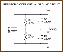
This is the type of voltage divider I used to split the 12V DC to +6V and -6V. Resistors were 4.7kohm and 1000uF caps. Does this mean my output impedance will be 4.7kohm for the supply ? Yes I change bias resistors to provide 2.5mA. Now I am searching my house for a 18V wall wart. Not sure if using two 9v wall wart to provide +9 and -9V will work.
I have so many things to experiment on this amp since its still on breadboard. Like adding cap across the biasing diodes (which I left out) to see what effect it has.
Last edited:
Tested the amp again with +9 and -9V power with the voltage divider split supply. The most immediate change was that the background in the music feels much darker with the higher rails.
On some songs, it feels like there is slightly more space between instruments. But this difference is subtle.
On some songs, it feels like there is slightly more space between instruments. But this difference is subtle.
This is the type of voltage divider I used to split the 12V DC to +6V and -6V. Resistors were 4.7kohm and 1000uF caps. Does this mean my output impedance will be 4.7kohm for the supply ? Yes I change bias resistors to provide 2.5mA. Now I am searching my house for a 18V wall wart. Not sure if using two 9v wall wart to provide +9 and -9V will work.
I have so many things to experiment on this amp since its still on breadboard. Like adding cap across the biasing diodes (which I left out) to see what effect it has.
The headphone output is relative to the virtual ground - so that has to go through 4k7. However, the bulk caps do provide some storage for large current transients. It works but you will get much more powerful bass with a true double rail power supply.
- Status
- Not open for further replies.
- Home
- Amplifiers
- Headphone Systems
- ESP HPA