Thanks for those additional plots showing more clearly the < 1mS HF reflections.
Can you estimate the distances between the diaphragm, dust covers, and grills? Is it the same for front and rear?
My dustcover test shown in Post#18 used front and rear dustcovers at the same distance(26mm) from the diaphragm and no grills.
Based on your outdoor measurement setup description, the ground reflection would be closer to 2mS...which actually seems to show up in your 1/3 octave wavelet plot but doesn't extend much above 4kHz. I guess that makes sense as grass wouldn't be a very good HF mirror. The 4mS reflection must be off the measurement equipment, perhaps laptop screen or chair.
Last edited:
The dust covers are 35 mm from the diaphragm, front and back
The grill is 65 mm from the diaphragm in the middle (vertically). It is closer to the sides, 40 mm.
The original louvre grill was used, not a flat metal so called pro grill.
I don't see how the equipment on the chair could have made a reflection, is was deliberately placed in the dead zone of the ESL. at least 2 meters away.
It is just a small object on a plastic bench with no arms rests, no back support, only a flat seat. But I could be wrong of course.
Thanks for the dimensions. I'll have to cogitate on those a bit to see how they may be related to the < 1mS reflections.
Your measurement setup looks great with the equipment in the deadzone of the dipole radiator...along with the operator no doubt.
I am about out of ideas for the source of the 4mS reflection, but it had to have come from somewhere.
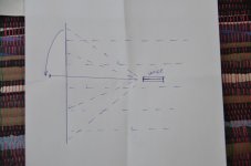
The only other thought that came to mind is perhaps from the mic stand. I'm not sure exactly what your stand looks like or how it was positioned. But if it was similar to attached images(not to scale), reflection off the support pole could have been the source. I have definitely experienced this and had to use foam to minimize it. Another less likely possibility of reflection from the base of the mic stand is also shown. Either one could produce the neccessary ~1.4m path length difference for the 4mS reflection.


Your measurement setup looks great with the equipment in the deadzone of the dipole radiator...along with the operator no doubt.
I am about out of ideas for the source of the 4mS reflection, but it had to have come from somewhere.
The only other thought that came to mind is perhaps from the mic stand. I'm not sure exactly what your stand looks like or how it was positioned. But if it was similar to attached images(not to scale), reflection off the support pole could have been the source. I have definitely experienced this and had to use foam to minimize it. Another less likely possibility of reflection from the base of the mic stand is also shown. Either one could produce the neccessary ~1.4m path length difference for the 4mS reflection.
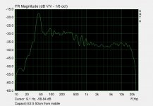
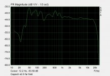
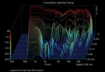

Nice ESL's! I havent seen them so did a search.I think they look great. Impressive size and great 40kHz bass extension.Capaciti E2.5 near field, far field and CSD.
Were there dust covers or reflection interfaces that might explain the CSD high frequency resonance bands? Thanks.
Idea behind replacing esl57 with Capaciti - segmented wire stator design so possible wider dispersion. Bass is more powerfull and extended - not sure if intristic resonance is damped (silkscreen?), see near field response. They are made very sturdy. They have external resistor sockets - 3R3 flatten high frequencies. Similar to Silberstatic?
Capaciti used to post here, providing useful tidbits of knowledge regarding wire ESL construction.
I don't recall him ever mentioning or posting pictures showing dustcovers.
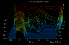
You might be interested in a CSD he had posted from one of his smaller panels. (Element 160s I believe)
https://www.diyaudio.com/community/threads/esls-have-bad-decay-plots.168069/post-2208750

You can also see similarly clean CSDs from a Capaciti review I had grabbed from somewhere...although the pdf resolution is pretty poor. 🙁
I don't recall him ever mentioning or posting pictures showing dustcovers.
You might be interested in a CSD he had posted from one of his smaller panels. (Element 160s I believe)
https://www.diyaudio.com/community/threads/esls-have-bad-decay-plots.168069/post-2208750
You can also see similarly clean CSDs from a Capaciti review I had grabbed from somewhere...although the pdf resolution is pretty poor. 🙁
Attachments
similarly clean CSDs from a Capaciti review
Wow. Those naked Capaciti panel waterfall plots are aspirational. They rule out the hypothesis that all ESL panels have inherent chaotic modes.
But the Capaciti CSD jzagadja posted looks like it might have reflections and the E2.5 has a sock and is 90mm deep:
BTW, the construction of the Capaciti panels looks EXACTLY like the old audiostatic panels. I was impressed with the design of them when I fixed an old ES-50 set. I'd say they are on the right track (based on my biases of course).
Sheldon
Sheldon
Capaciti seems to have a panel design that has conquered resonance. Despite the Ausdiostatic having similar construction it doent look as clean as the Capaciti CSD ,but could that just be a measurement and plotting scale artefact?
Heres the Audiostatic ES-100 loudspeaker. The panel has no covers and looks very open; yet there is some high frequency energy. Is this an indication of high frequency chaotic modes? Or is the plot scale just very sensitive?


Capacity ESL - unkown finished model with a speaker cloth cover. Super clean above 5kHz but the scale is obscured with the poor quality image scan.


Could the bands at about 2kHz and 4kHz (be the speaker cloth setting up half wave and full wave resonance?
Some Capaciti commercial models had a depth of 90mm and

Heres the Audiostatic ES-100 loudspeaker. The panel has no covers and looks very open; yet there is some high frequency energy. Is this an indication of high frequency chaotic modes? Or is the plot scale just very sensitive?
Capacity ESL - unkown finished model with a speaker cloth cover. Super clean above 5kHz but the scale is obscured with the poor quality image scan.
Could the bands at about 2kHz and 4kHz (be the speaker cloth setting up half wave and full wave resonance?
Some Capaciti commercial models had a depth of 90mm and
Last edited:
Capaciti design:

- Very thin membrane foil (0.0045mm) for the fastest signal reproduction
- Thin, insulated wire stators for homogeneous drive and best flashover resistance
- Small and even membrane spacing for high efficiency with a high maximum level at the same time
- Separate and narrow segment for high-frequency reproduction improves lateral radiation
Thanks for the dimensions. I'll have to cogitate on those a bit to see how they may be related to the < 1mS reflections.Thanks for the dimensions. I'll have to cogitate on those a bit to see how they may be related to the < 1mS reflections.
Your measurement setup looks great with the equipment in the deadzone of the dipole radiator...along with the operator no doubt.
I am about out of ideas for the source of the 4mS reflection, but it had to have come from somewhere.
The only other thought that came to mind is perhaps from the mic stand. I'm not sure exactly what your stand looks like or how it was positioned. But if it was similar to attached images(not to scale), reflection off the support pole could have been the source. I have definitely experienced this and had to use foam to minimize it. Another less likely possibility of reflection from the base of the mic stand is also shown. Either one could produce the neccessary ~1.4m path length difference for the 4mS reflection.View attachment 1025516View attachment 1025517
Your measurement setup looks great with the equipment in the deadzone of the dipole radiator...along with the operator no doubt.
I am about out of ideas for the source of the 4mS reflection, but it had to have come from somewhere.
The only other thought that came to mind is perhaps from the mic stand. I'm not sure exactly what your stand looks like or how it was positioned. But if it was similar to attached images(not to scale), reflection off the support pole could have been the source. I have definitely experienced this and had to use foam to minimize it. Another less likely possibility of reflection from the base of the mic stand is also shown. Either one could produce the neccessary ~1.4m path length difference for the
It seems to me that the reflections here are of secondary importance, and the main thing is that the planar emitter is not a point emitter, and this is its main trouble. After all, the signal comes to the microphone or ear from different points of a large emitter at different times.Thanks for the dimensions. I'll have to cogitate on those a bit to see how they may be related to the < 1mS reflections.
Your measurement setup looks great with the equipment in the deadzone of the dipole radiator...along with the operator no doubt.
I am about out of ideas for the source of the 4mS reflection, but it had to have come from somewhere.
The only other thought that came to mind is perhaps from the mic stand. I'm not sure exactly what your stand looks like or how it was positioned. But if it was similar to attached images(not to scale), reflection off the support pole could have been the source. I have definitely experienced this and had to use foam to minimize it. Another less likely possibility of reflection from the base of the mic stand is also shown. Either one could produce the neccessary ~1.4m path length difference for the 4mS reflection.View attachment 1025516View attachment 1025517
Attachments
Peter Walker thought of that too and created ESL 63.It seems to me that the reflections here are of secondary importance, and the main thing is that the planar emitter is not a point emitter, and this is its main trouble. After all, the signal comes to the microphone or ear from different points of a large emitter at different times.
Unfortunately this is not the case, for the high frequencies to emit correctly, the radiator has to be one inch or less in size.Peter Walker thought of that too and created ESL 63.
And in the ESL 63 it is much larger.
And the reason is well known - an electrostatic of such a small size can't give enough sound volume. You need a much larger radiating area, that's the compromise.
If you want a point emitter then an ESL planar is certainly a problem.the planar emitter is not a point emitter, and this is its main trouble.
After all, the signal comes to the microphone or ear from different points of a large emitter at different times.
Could it be the wave mechanics of planar waves dont behave as independent point sources with variant vectors?
Trying to conceive of a planar as a number of distant independent point sources is misleading:
as that simplistic model breaks down with a planar. To conceive a planar as multiple point sources needs to use dx:
So the planar wave does not have timing issues if the theory is right.
Lets check some data. Impulse response will reveal timing issues:
"Note the excellent right-triangle shape of the panel's arrival, which suggests a time-coherent presentation"
Fig.12 InnerSound Eros Mk.III, step response on mid-panel axis at 50" of electrostatic panel (red trace) and woofer (blue). (5ms time window, 30kHz bandwidth.)
quod erat demonstrandum
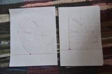
A point source of sound at high frequencies is needed not only by me, but also by all listeners of phonograms in stereo format. I'll try to justify the high-frequency driver that I made myself. We know that the length of the sound wave at 16kHz is 20mm, which in turn means that if we have a 20mm driver, then the sound up to 16kHz will be broadly directional and only after 16kHz it will be narrowly directional. Therefore, I made my driver from a 20mm wide strip. Also, do not forget that the stereo format only works in the horizontal plane, so a point source of sound (20mm) is important for us, primarily in the horizontal plane. But since the ESL is very weak in sensitivity (volume level), we are forced to increase the radiation area by stretching the emitter strip in the vertical plane, which is not so terrible for our ear in stereo format. We know that the stereo image is formed by two sound sources exclusively in the horizontal plane depicting phantom, apparent sources of sound. When I made a strip 20mm wide and 1900mm high. hanging it on the bar, it turned out that there was a catastrophic lack of sound volume, such a driver played too quietly relative to the bass driver. That is, the main part of the sound coming from such a long driver went past my ear (microphone) and to fix this I bent a long strip along a vertical plane and then the sound from the entire length of the strip began to come to the ear (microphone) at a time and in a direction, which means the level volume increased several times. As a result, I got a point sound source in the horizontal plane (which is very important for a stereo format), but a directional and time-accurate sound source in the vertical plane. That is, such a driver is critical for moving my ear in a vertical plane, I can listen to it just sitting on the couch, not getting up. Why do I write so much about a point and broadband driver? - because such a driver is able to work without coloring and frequency interference. The large area of the driver forms the directivity of certain frequencies, depending on the size of the driver, which means a strong coloration of the sound. This is all from my own practice. Sorry for the confusion in the text, I write through Google.
Attachments
- Home
- Loudspeakers
- Planars & Exotics
- ESL high frequency chaotic modes?