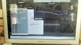
So I was really pleased that I got the ESL panel working last night. But unfortunately the sound was pretty harsh.
So I spent some time applying a system wide EQ to my mac output. This really improved things.
A couple of other problems. Distortion - which initially I thought was amp related (I started with an integrated NAD amp). So I swapped this over to a mono Quad amp. But it doesn't seem to be down to the amp. Volume - could do with just a bit more volume! Originally I anticipated a 1.55mm gap between wires and membrane. But I calculate that I ended up with 1.9mm.
A couple of errors I think I made. I used multi-strand cable and it hasn't maintained it's spacing. Perhaps I should have glued with more tension.
Also I don't think I applied enough tension to the membrane.
Another issue - I didn't factor in that the rear stator would be a mirror image, hence the middle section of cables are 2mm out!
Going to try and find some semi rigid, PVC solid core cable.
Attachments
My first segmented ESL used welding rod conductors on a plastic light diffuser grid, with horizontal diaphragm supports. It sounded quite good, and I can't say that other panels I've built with vertical supports sound better, for that reason.
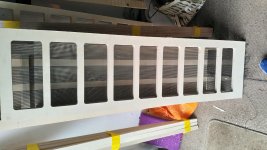
The fact that the wires in your panel are arranged in three vertical groups to accept two vertical spacers, but you used horizontal supports, isn't the ideal setup but it probably doesn't affect the sound quality-- only reduces the efficiency.
By reduced efficiency; I'm referring to the open diaphragm areas (open spaces between wire groups) that are not being driven by wires. Also; the wire area under the horizontal supports is "stray capacitance". That is; capacitance that loads your amplifier but can't contribute to sound output.
Had you used vertical spacers, to match the wire arrangement; all of the diaphragm would be utilized, and the panel would have almost no stray capacitance (only a small amount where the wires glue to the frame at the panel ends, but that can't be avoided).
Since you invited a critique of your panel; I will point out that you might have been better off using single strand wire, which supports itself and keeps itself straight in the relaxed state.
There's nothing wrong with using stranded wire but it needs a bit of tension. If fact; stranded wire is preferred by the DIY ESL community in Finland (they build wonderful speakers). Stranded wire would be better at dampening resonances, and it doesn't need to be stretched straight in a jig. But it does need to be in moderate tension in the stator, in order to keep it straight and prevent having loose wire protruding into the diaphragm-to-stator gap where it could clash with the diaphragm.
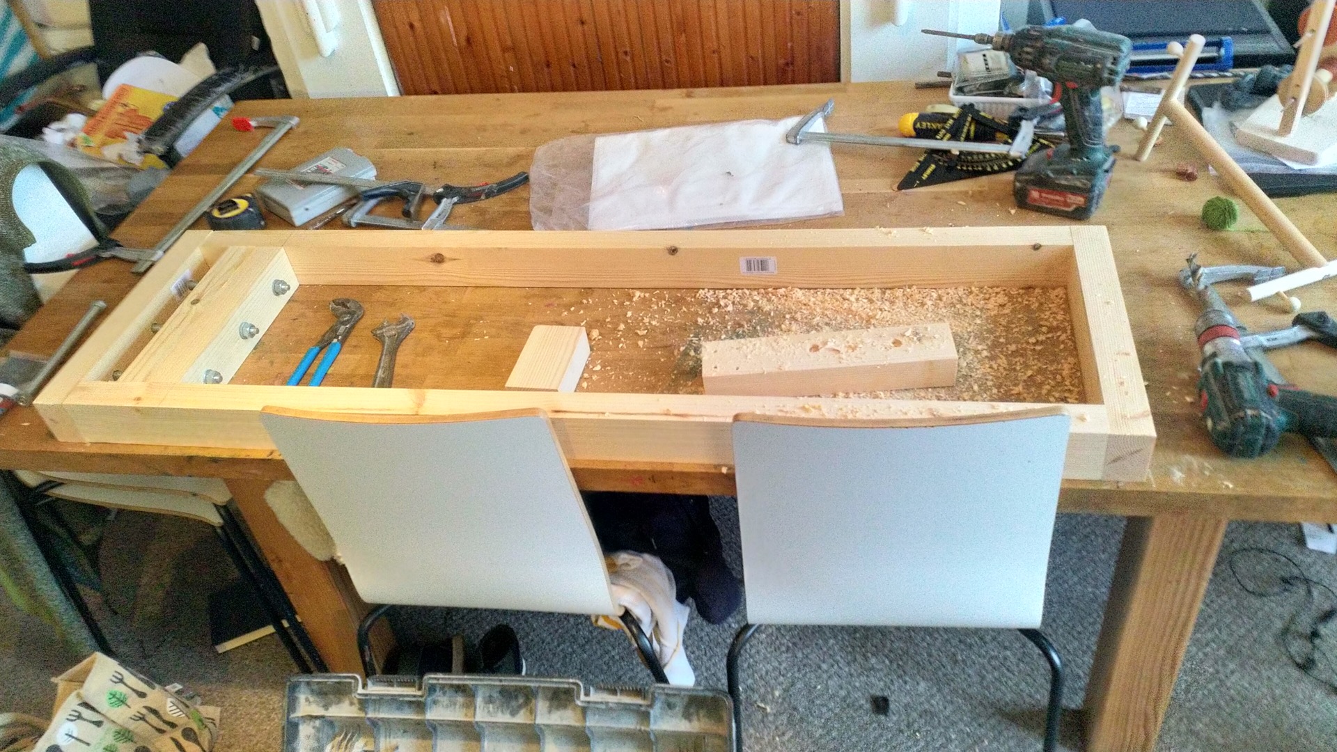
You're frame looks very strong, which is needed to keep stranded wires in tension. I don't know whether your wires are in tension but they look relatively straight so I'm thinking they must be in some degree of tension. Stranded wire in sufficient tension works very well in an ESL.
All in all; I'd say you did very well for a first effort. My first ESL played for about 30 seconds before the perf metal stators started arcing and shut down my amp (if you smell ozone; you know you've got a problem!)
The fact that the wires in your panel are arranged in three vertical groups to accept two vertical spacers, but you used horizontal supports, isn't the ideal setup but it probably doesn't affect the sound quality-- only reduces the efficiency.
By reduced efficiency; I'm referring to the open diaphragm areas (open spaces between wire groups) that are not being driven by wires. Also; the wire area under the horizontal supports is "stray capacitance". That is; capacitance that loads your amplifier but can't contribute to sound output.
Had you used vertical spacers, to match the wire arrangement; all of the diaphragm would be utilized, and the panel would have almost no stray capacitance (only a small amount where the wires glue to the frame at the panel ends, but that can't be avoided).
Since you invited a critique of your panel; I will point out that you might have been better off using single strand wire, which supports itself and keeps itself straight in the relaxed state.
There's nothing wrong with using stranded wire but it needs a bit of tension. If fact; stranded wire is preferred by the DIY ESL community in Finland (they build wonderful speakers). Stranded wire would be better at dampening resonances, and it doesn't need to be stretched straight in a jig. But it does need to be in moderate tension in the stator, in order to keep it straight and prevent having loose wire protruding into the diaphragm-to-stator gap where it could clash with the diaphragm.
You're frame looks very strong, which is needed to keep stranded wires in tension. I don't know whether your wires are in tension but they look relatively straight so I'm thinking they must be in some degree of tension. Stranded wire in sufficient tension works very well in an ESL.
All in all; I'd say you did very well for a first effort. My first ESL played for about 30 seconds before the perf metal stators started arcing and shut down my amp (if you smell ozone; you know you've got a problem!)
Last edited:
Hey Charlie - thanks for the feedback.
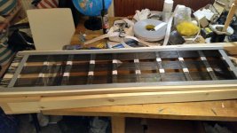
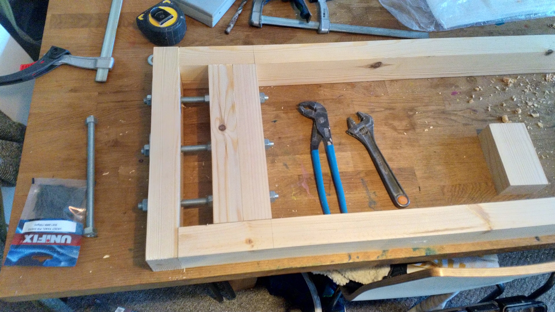
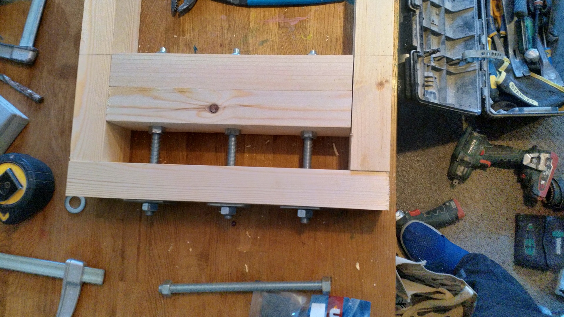
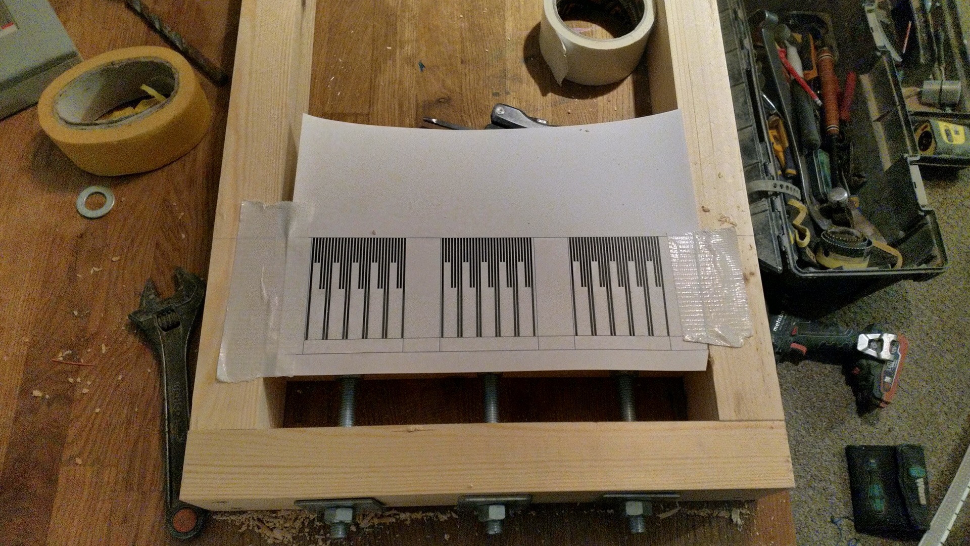
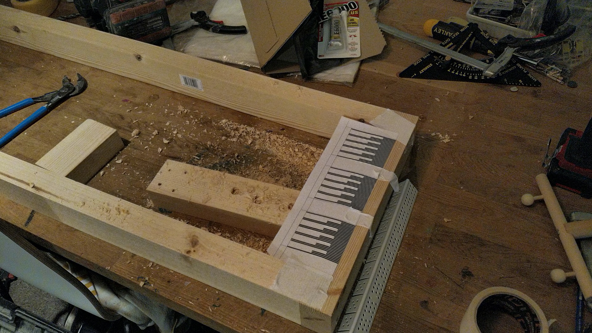
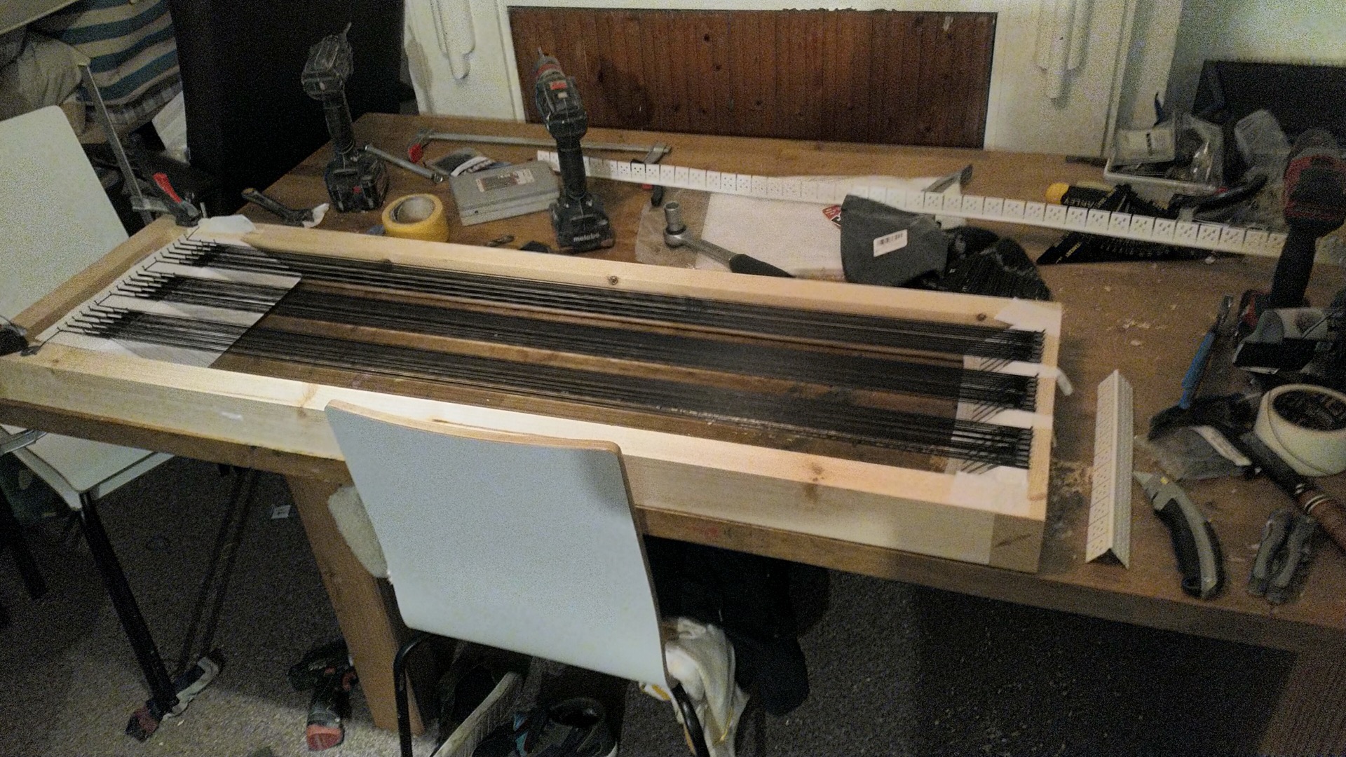
I've just taken delivery of 500m of solid core. Thinking of rewiring the panels so that there are no vertical gaps. I'm attaching a picture which shows how I used the double sided VHB tape - it doesn't fully cover the horizontal supports
I'm wondering if I've damaged something on the circuit board though. I'm getting fairly ok. volume, but definitely not ear splitting. Perhaps that's down to the membrane/wire distance?
Attachments
Assuming you are crossing the panel over above 200Hz (the dual 50VA toroidal transformer setup is only good for >200Hz) and the diaphragm to stator spacing is about 1.5mm (.063"), then you should have plenty of sound pressure.
Last edited:
At the moment I haven't implemented any segmentation. Are their any differences if I connect the end of each stater wire back to the toroidals? Presently the ends just terminate..
I'm not sure what you mean by the "end of each stator wire" because I don't know whether you've cut any of the wire loops.
Referring to my wire schematic below; the wire is looped around the pins in the stretching jig as is a single uncut wire wire with two ends.
Referring to the upper portion of the sketch:
If none of he wire loops have been cut, and either end (or both ends) of that single wire is connected to the to the transformers; then the entire stator is powered, but not segmented.
The lower portion of the sketch shows how I cut that single looped wire into (15) separate segments. Electrically; each segment is a single wire, even though we may refer to it as a 6-wire group because it's looped into six vertical portions.
Then; to segment the panel, we need only connect one end of each wire segment, with resistors inserted between the segments, as shown. You might have noticed that I drew the center wire segment with both its ends connecting to the transformer, but I only showed it this way for symmetry. Only one end needs to be connected, and it makes no difference if both ends are connected.
At first glance; having only one end of each wire segment connecting to the transformer appears to be an open circuit because we don't see a second physical wire leading back to the transformer-- but this is misleading: The circuit is a capacitor, and the total length of each wire segment forms one electrode of the capacitor. The connection which closes the circuit is from the wire group/electrode> thru the ionized air gap > to the diaphragm (opposite electrode) > to the transformer center tap.
Since you've said your panel has low output; I'm wondering if you had cut the wire loops and only had a portion of them connecting to the transformers (?)
Attachments

Last edited:
I see there are 4 photo's missing, would it be possible to repost them?Thanks to @CharlieM and @bolserst firstly.
I've started my journey on building some ESLs mainly inspired by Jazzman's blog.
A little bit of background, I got interested in ESLs back in 2014. Went to listen to some MLs and ended up buying some parts back in 2014. At the time I was thinking about perforated panels, but actually ended up buying 500 metres of wire. Things didn't progress much and I gave the materials away.. I got the bug again a few weeks ago (2021)! Managed to get the materials back and ordered the rest of the ingredients and made a start today. Really pleased!
Thought I'd post some pictures and try and keep a record of progress on this thread.
I don't think anything will be ground breaking here, but might be interesting for other future builders who want some inspiration and some pictures to refer to.
An externally hosted image should be here but it was not working when we last tested it.[/URL]
An externally hosted image should be here but it was not working when we last tested it.[/URL]
An externally hosted image should be here but it was not working when we last tested it.[/URL]
An externally hosted image should be here but it was not working when we last tested it.[/URL]
Hi Mystroe,
Hang in there. I have to say every mistake you are making, I have made as well. It is a process getting through your first build, but it is definitely worth it. Along the way I have had mislabeled transformer polarities, a diaphragm not tensioned enough, welding rods not supported securely, a short in the HV supply, your name it. Knock them down one at a time and you will have a very worthwhile result. Getting help from Charlie is a great boon - he knows whatof he speaks.
Hang in there. I have to say every mistake you are making, I have made as well. It is a process getting through your first build, but it is definitely worth it. Along the way I have had mislabeled transformer polarities, a diaphragm not tensioned enough, welding rods not supported securely, a short in the HV supply, your name it. Knock them down one at a time and you will have a very worthwhile result. Getting help from Charlie is a great boon - he knows whatof he speaks.
- Home
- Loudspeakers
- Planars & Exotics
- ESL Build based on Jazzman's